Abstract
This disclosure describes a vacuum gripper array incorporating per-pad isolation to prevent system vacuum collapse when engaging loads with varying porosity or incomplete coverage. The arrangement utilizes individual check valves for each gripper pad, a vacuum reservoir, and a control unit. It details how the system acquires, holds, and releases loads, including mechanisms for detecting uncovered pads and a controlled release sequence to mitigate load displacement. This design addresses the challenge of reliably handling loads where one or more gripper pads might experience significant leakage, which typically compromises the entire vacuum system's integrity.
1. Technical Field
[0001]The present disclosure relates to robotic end effectors, specifically vacuum gripping systems utilized in automated material handling, assembly, and packaging applications. More particularly, it concerns vacuum gripper arrangements designed to reliably manipulate loads that exhibit varying degrees of surface porosity or may not present a consistently flat or complete surface for vacuum engagement.
2. Technical Context
[0002]Conventional vacuum gripping systems often employ a centralized vacuum source connected to multiple suction cups or pads via a common manifold. While effective for rigid, non-porous, and consistently shaped loads, this approach presents significant challenges when handling items that are porous, irregularly shaped, or when a portion of the gripper array might not fully engage the load. For instance, handling stacks of cardboard cartons, fabric layers, or items with perforations can lead to significant air leakage through one or more individual gripper pads. In a common manifold system, a single leaking pad can reduce the vacuum level across the entire array below the required threshold, causing the entire load to be dropped, leading to operational inefficiencies and potential damage to the load. The problem is exacerbated in applications requiring high pick-and-place rates where precise and reliable load acquisition is critical. There is a need for a vacuum gripping solution that can maintain sufficient gripping force even when some pads are compromised by leakage or incomplete surface contact.
3. System Overview
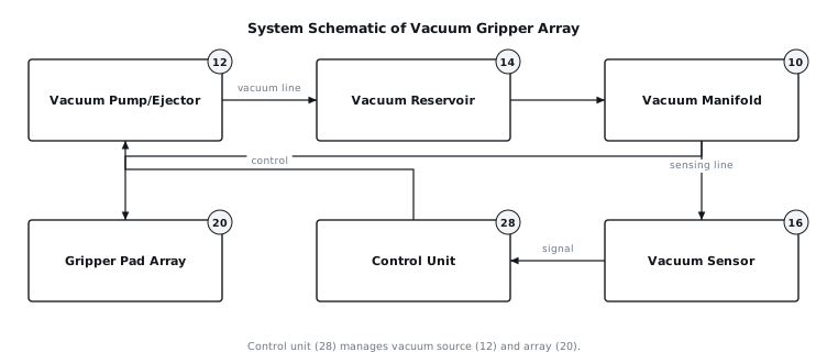
[0003]The disclosed system comprises a vacuum gripper pad array (20) configured for handling loads, particularly those with mixed porosity or irregular engagement surfaces. It integrates a central vacuum source, a manifold (10), a vacuum reservoir (14), and a control unit (28) with a plurality of individual gripper pads (22), each equipped with a dedicated check valve (24). The check valves (24) are strategically placed to isolate any individual pad (22) that experiences excessive air leakage from the rest of the vacuum system. A vacuum sensor (16) monitors the system vacuum level within the manifold (10) and provides feedback to the control unit (28). The control unit (28) manages the vacuum supply and initiates a controlled release sequence. This architecture ensures that the overall vacuum integrity is maintained even if several pads are exposed to atmospheric pressure or are engaging highly porous sections of a load. An overall system schematic is shown in FIG. 1.
4. Components
[0004]The system consists of the following primary components:
[0005]
- Vacuum Manifold (10): A central plenum or network of channels that distributes vacuum from the vacuum source to the individual gripper pads (22) and connects to the vacuum reservoir (14) and vacuum sensor (16).
- Vacuum Pump/Ejector (12): A device, such as a rotary vane pump, side-channel blower, or pneumatic ejector, responsible for generating and maintaining the required vacuum level within the system. The selection is based on required flow rate and ultimate vacuum.
- Vacuum Reservoir (14): A sealed volume connected to the vacuum manifold (10). Its primary function is to store vacuum energy, providing a buffer against sudden changes in vacuum demand and ensuring a stable vacuum level during load acquisition and transport.
- Vacuum Sensor (16): A transducer that measures the absolute or differential pressure within the vacuum manifold (10) and transmits this information to the control unit (28). It typically provides an analog or digital signal proportional to the vacuum level.
- Control Valve (18): A pneumatically or electrically actuated valve situated between the vacuum pump/ejector (12) and the vacuum manifold (10). It regulates the connection of the vacuum source to the system.
- Gripper Pad Array (20): An assembly comprising multiple individual gripper pads (22) arranged in a planar configuration. The array structure facilitates simultaneous engagement with a larger surface area of the load.
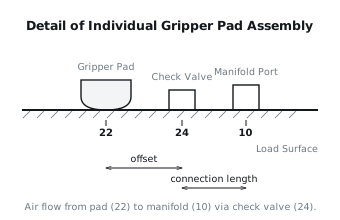
- Individual Gripper Pad (22): A suction cup or pad, typically made of an elastomeric material, designed to create a sealed cavity against a load surface when vacuum is applied. Each pad (22) connects to the vacuum manifold (10) via a dedicated check valve (24). A detailed view of a single pad assembly is shown in FIG. 2.
- Check Valve (24): A one-way valve positioned in the pneumatic line between each individual gripper pad (22) and the vacuum manifold (10). It is designed to open when the vacuum level within the pad (22) cavity (i.e., between the pad and the load) exceeds a predetermined threshold below the manifold vacuum, allowing air to be evacuated. Conversely, it closes when the vacuum in the pad (22) cavity rises significantly (approaches atmospheric pressure) due to leakage, thereby preventing air ingress from that pad into the main manifold (10).
- Pneumatic Control Unit (28): An electronic controller or programmable logic controller (PLC) that receives input from the vacuum sensor (16) and other system sensors, processes control logic, and outputs commands to the vacuum pump/ejector (12), control valve (18), and release valve (26).
- Atmospheric Vent Valve (30): A valve connected to the vacuum manifold (10) that, when actuated, rapidly connects the manifold to atmospheric pressure, facilitating a quick release of the load.
- Pressure Equalizing Channels (32): Small-diameter channels or orifices that may be incorporated into the check valve (24) or manifold connection to slowly equalize pressure across the check valve when the system is de-energized, ensuring all pads are ready for the next cycle.
5. Operation
[0006]The system's operation involves several phases: initialization, load acquisition, load transport, and load release.
[0007]Initialization: Upon system power-up, the control unit (28) activates the vacuum pump/ejector (12) and opens the control valve (18) to evacuate the vacuum manifold (10) and vacuum reservoir (14). The vacuum sensor (16) continuously monitors the vacuum level. This phase continues until the system vacuum reaches a predefined setpoint, for example, 70 kPa below atmospheric pressure. During this initial evacuation, all check valves (24) are open due to the pressure differential between the atmosphere and the evacuating manifold, allowing air to be drawn from the pads (22).
[0008]Load Acquisition: Once the target vacuum level is achieved in the vacuum reservoir (14) and manifold (10), the gripper pad array (20) is lowered towards the target load. As the individual gripper pads (22) make contact with the load surface, they form sealed cavities. The vacuum within these sealed cavities rapidly decreases due to the action of the vacuum pump/ejector (12) and the open check valves (24). Pads (22) that contact non-porous sections of the load or make good seals will quickly achieve a strong vacuum. Pads (22) that contact porous sections or fail to make adequate contact will experience significant air leakage, preventing a strong vacuum from forming within their individual cavities. The check valves (24) are designed with a specific crack pressure; if the vacuum within a pad's cavity fails to reach a level lower than the manifold vacuum by this crack pressure, the check valve (24) will close, isolating that leaking pad (22) from the vacuum manifold (10). This prevents the leak from compromising the overall system vacuum. The control unit (28) continuously monitors the manifold vacuum via the vacuum sensor (16). If the manifold vacuum remains above a minimum operational threshold after a set engagement time, the control unit (28) signals successful load acquisition.
[0009]Load Transport: After successful acquisition, the control unit (28) may de-activate the vacuum pump/ejector (12) if the vacuum reservoir (14) is sufficiently sized to maintain the vacuum during transport. The control valve (18) remains open, connecting the manifold (10) to the reservoir (14). The isolated check valves (24) maintain vacuum within the system even if some pads (22) are leaking. The vacuum sensor (16) provides ongoing feedback, and if the system vacuum drops below a critical threshold due to sustained leakage or an unexpected event, the control unit (28) can re-activate the vacuum pump/ejector (12) or trigger a fault condition.
[0010]Load Release: To release the load, the control unit (28) first deactivates the vacuum pump/ejector (12) (if active) and closes the control valve (18) to isolate the manifold (10) from the vacuum source and reservoir (14). Subsequently, it opens the atmospheric vent valve (30), which rapidly introduces atmospheric air into the vacuum manifold (10). This equalizes the pressure within the manifold (10) and the connected pads (22) that had successfully engaged the load. The sudden ingress of air breaks the vacuum seal, allowing the load to be released. This sequence is designed to prevent the load from being "thrown" or displaced horizontally by residual vacuum forces, which can occur if the vacuum is released unevenly or too slowly across a large array. The pressure equalizing channels (32) ensure that any check valves (24) that closed during operation will slowly equalize across their membranes, preparing them for the next pick cycle.
[0011]Fault or Interruption: In the event of a power failure, the control valve (18) and atmospheric vent valve (30) are typically configured to fail-safe, either maintaining the current state for a short period using the reservoir (14) or allowing a controlled bleed to atmospheric pressure. If the vacuum sensor (16) detects a vacuum level below the safe operational threshold during transport, the control unit (28) can issue a warning, halt machine motion, or initiate an emergency controlled release sequence to prevent unintended dropping of the load.
6. Example Embodiments
[0012]Embodiment 1: This embodiment utilizes simple spring-loaded poppet-style check valves (24), each with a fixed crack pressure of approximately 15 kPa. The vacuum pump/ejector (12) operates continuously during load acquisition and transport to maintain the manifold vacuum. The control unit (28) monitors the manifold vacuum via the vacuum sensor (16) and activates a visual indicator if the vacuum drops below 60 kPa below atmospheric pressure. The vacuum reservoir (14) is sized to provide 3 to 5 seconds of hold time if the vacuum source is interrupted. Release is initiated by a single atmospheric vent valve (30) for the entire manifold.
[0013]Embodiment 2: This configuration incorporates solenoid-actuated check valves (24) instead of passive mechanical check valves. Each pad (22) also has a small, dedicated vacuum switch (not shown) connected to the control unit (28). During load acquisition, the control unit (28) individually monitors the vacuum level at each pad (22). If a pad's vacuum switch indicates insufficient vacuum (e.g., above 30 kPa below atmospheric pressure) after a set contact time, the control unit (28) commands its associated solenoid-actuated check valve (24) to close, actively isolating it. This allows for more precise control over isolation and can adapt to different load porosity profiles. The release sequence involves opening all solenoid-actuated check valves (24) to atmospheric pressure simultaneously, along with the main atmospheric vent valve (30), ensuring rapid and uniform pressure equalization across all pads.
[0014]Embodiment 3: This embodiment segments the gripper pad array (20) into two or more independent zones, each with its own sub-manifold, vacuum sensor (16), and dedicated control valve (18) and atmospheric vent valve (30). Each zone still employs per-pad passive check valves (24) as in Embodiment 1. The control unit (28) independently controls the vacuum for each zone. This allows for gripping loads with highly disparate porosity characteristics across their surface, or for picking up multiple smaller, independent items simultaneously. For example, one zone might be dedicated to a highly porous cardboard box, while another handles a sealed plastic container. The vacuum levels for each zone can be tuned independently.
7. Alternative Configurations
[0015]The individual check valves (24) can be implemented using various designs, such as diaphragm valves, ball valves, or duckbill valves, chosen based on flow rate requirements, cracking pressure, and resistance to contamination. Instead of a single vacuum sensor (16) in the manifold, multiple vacuum sensors could be distributed across the manifold or even at the inlet of groups of pads to provide more granular vacuum feedback to the control unit (28). The vacuum pump/ejector (12) could be replaced by a centralized vacuum supply system in a facility, with the control valve (18) managing the connection to the end effector. The vacuum reservoir (14) could be integrated into the manifold (10) structure itself, potentially using hollow structural members.
8. Parameter Variations
| Parameter | Range | Effect of Moving within Range |
|---|---|---|
| Pad diameter | 10 mm to 150 mm | Larger pads increase individual gripping force but require more flow for evacuation and are less flexible on irregular surfaces. Smaller pads offer better conformation but lower individual force. |
| Vacuum level | 40 kPa to 90 kPa below atmospheric | Higher vacuum levels increase gripping force but demand more power and can be detrimental to delicate loads. Lower vacuum is more energy efficient but reduces holding capacity. |
| Reservoir volume | 0.5 L to 20 L | Larger volumes provide greater vacuum stability during dynamic operations or momentary leaks, extending hold time during power interruptions. Smaller volumes respond faster to pump action. |
| Check valve crack pressure | 5 kPa to 25 kPa | Lower crack pressure allows more pads to contribute to initial vacuum. Higher crack pressure ensures more aggressive isolation of leaking pads but may prevent marginally functional pads from activating. |
| Array size (number of pads) | 4 to 100+ | More pads distribute the load over a larger area, increasing total lifting capacity. Increased complexity and weight for larger arrays. |
| Cycle time | 0.5 s to 10 s | Shorter cycle times demand faster vacuum generation and release mechanisms. Longer times allow for more stable vacuum conditions and gentler handling. |
9. Additional Implementations
[0017]This per-pad isolation principle can be extended to other forms of multi-point grippers where localized failure would compromise the entire gripping action. For example, it could be adapted to magnetic grippers where individual electromagnets might fail or encounter non-magnetic sections of a load, by using current-limiting or fault-detection circuits per electromagnet. The control unit (28) can integrate with a vision system to pre-determine regions of a load likely to be porous or irregular, allowing for adaptive control of individual pad engagement or selective activation of isolation mechanisms in advanced embodiments. The system could also incorporate individual flow sensors at each pad connection point to provide more precise feedback to the control unit (28) regarding the leakage status of each pad, enabling predictive maintenance or dynamic adjustment of vacuum levels.
10. Figures