Abstract
This disclosure describes a zero point clamping interface featuring an integrated seating confirmation port. The system provides a mechanism to verify that a pallet is correctly seated within the clamping unit prior to commencing machining operations. It addresses the issue of undetected non-seated pallets, which can lead to machining inaccuracies despite appearing correctly clamped. An air-based sensing circuit detects the presence of a sealed interface between the pallet and the clamping unit, generating distinct pressure signatures for seated and unseated conditions to enable an interlock with a machine tool's operation.
1. Technical Field
[0001]This disclosure relates to workholding systems, specifically zero point clamping arrangements used for rapidly exchanging workpieces or fixtures on machine tools. More particularly, it concerns methods and apparatus for verifying the correct seating of a clamped workpiece or fixture pallet.
2. Technical Context
[0002]In precision manufacturing, workholding systems like zero point clamping enable quick and accurate positioning of workpieces or fixture pallets on machine tools. These systems often rely on mechanical clamping forces to secure the pallet to a base unit. A critical requirement for achieving machining accuracy is that the pallet must be fully seated against the clamping unit's datum surfaces. If a pallet is clamped but not correctly seated, for instance due to contamination or misalignment, the workpiece mounted on it will be positioned incorrectly relative to the machine's coordinate system. This condition can lead to machining out of tolerance, producing scrap parts that are visually indistinguishable from correctly machined parts until inspection, or causing tool damage. Current clamping systems typically confirm only the clamping state, not the seating state, leaving a potential undetected error source.
3. System Overview
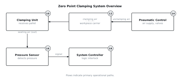
[0003]The disclosed system integrates a seating confirmation capability into a zero point clamping interface. As depicted in FIG. 1, a clamping unit (10) receives and secures a pallet (12). The system incorporates a pneumatic control unit (14) that manages both the clamping/unclamping operations and a dedicated air-based seating confirmation circuit. This circuit routes low-pressure air to an interface port on the clamping unit (10) which interacts with the pallet (12). A pressure sensor (16) monitors the pressure within this circuit. The output from the pressure sensor (16) is communicated to a system controller (18), which interprets the pressure signature to determine if the pallet (12) is correctly seated. Based on this determination, the system controller (18) can interlock with the machine tool's spindle operation, preventing machining if an unseated condition is detected.
4. Components
[0004]The primary components of the system include:
[0005]
- Clamping Unit (10): This unit is typically mounted to a machine tool table. It comprises a base structure, one or more clamping mechanisms (28) that engage with corresponding features on the pallet (12), and internal fluidic passages for clamping actuation and seating confirmation. The clamping unit (10) includes a datum surface against which the pallet (12) is intended to seat and at least one seating confirmation port (26).
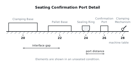
- Pallet (12): This is a modular base plate or fixture designed to hold a workpiece. It features mating elements for the clamping mechanisms (28) of the clamping unit (10) and a precisely machined contact surface that interfaces with the datum surface of the clamping unit (10). Crucially, the pallet (12) incorporates a sealing ring (24) or similar elastomeric gasket around the seating confirmation port (26) area, as shown in FIG. 2.
- Pneumatic Control (14): This module supplies pressurized air to the clamping unit (10) for both clamping actuation and the seating confirmation circuit. It typically includes an air supply line, pressure regulators to set appropriate operating pressures, solenoid valves for controlling air flow, and filters to ensure air cleanliness. The pneumatic control (14) provides a regulated, low-pressure air supply, for example, 0.5 to 1.5 bar, to the seating confirmation port (26).
- Pressure Sensor (16): A transducer capable of measuring the pneumatic pressure within the seating confirmation circuit. This sensor (16) provides an analog or digital output signal proportional to the detected pressure. The sensor (16) is selected for sensitivity in the low-pressure range, for example, 0 to 2 bar, and rapid response time.
- System Controller (18): This electronic unit processes the signal from the pressure sensor (16). It compares the sensed pressure value against predefined thresholds to determine the seating status. The controller (18) generates an output signal to indicate seated or unseated conditions, and critically, it provides an interlock signal to the machine tool's main control unit, preventing or stopping spindle operation if an unseated condition is present.
- Sealing Ring (24): An elastomeric or compliant seal, such as an O-ring or custom-profile gasket, integrated into the pallet (12) or clamping unit (10). As shown in FIG. 2, its purpose is to create an airtight seal around the seating confirmation port (26) when the pallet (12) is correctly seated.
- Seating Confirmation Port (26): A small diameter bore or channel within the clamping unit (10) that opens to the interface surface. When the pallet (12) is seated, this port (26) is sealed by the pallet's contact surface and the sealing ring (24). Air is introduced into this sealed volume for pressure sensing.
5. Operation
[0006]The operation of the system involves several distinct phases:
[0007]Start-up / Pallet Loading: Upon placement of a pallet (12) onto the clamping unit (10), the pneumatic control (14) initiates the clamping sequence. Air pressure is applied to the clamping mechanisms (28) within the clamping unit (10), causing them to engage with the pallet (12) and draw it downwards towards the datum surface. Once the pallet (12) is mechanically clamped, the seating confirmation sequence begins.
[0008]Seating Confirmation Cycle: The pneumatic control (14) opens a valve, supplying low-pressure air into the seating confirmation port (26) within the clamping unit (10). This air enters the small volume created between the clamping unit (10) and the pallet (12) in the vicinity of the port (26). The pressure sensor (16) continuously monitors the pressure in this circuit.
[0009]
- Seated Condition: If the pallet (12) is correctly seated against the datum surface of the clamping unit (10), the sealing ring (24) on the pallet (12) forms an effective seal around the seating confirmation port (26). The introduced air quickly pressurizes this small, sealed volume. The pressure sensor (16) detects a rapid rise in pressure to a pre-set value, for example, 0.8 to 1.2 bar. This pressure signature, characterized by a rapid pressure increase and stabilization at the supply pressure, indicates a successful seating. The system controller (18) interprets this as "seated" and permits machine operation.
- Unseated Condition: If the pallet (12) is not correctly seated, due to contamination (e.g., a chip or debris between the surfaces) or misalignment, the sealing ring (24) will not form a complete seal around the seating confirmation port (26). When air is introduced, it will escape through the gap or incomplete seal. The pressure sensor (16) will detect either a very low pressure (e.g., below 0.1 bar) or a slow, incomplete pressure rise, indicating a leakage path. This pressure signature, characterized by low or unstable pressure, indicates an "unseated" condition. The system controller (18) interprets this as "unseated" and activates the interlock.
[0010]Contamination Handling: The small air flow through the seating confirmation port (26) during the initial phase can also serve to purge minor debris from the interface area. If a small contaminant is present but does not fully obstruct the seal, the outgoing air might dislodge it. If the contaminant is significant, it will prevent a proper seal, leading to an "unseated" detection.
[0011]Interlock with Spindle: Upon detecting an "unseated" condition, the system controller (18) sends a signal to the machine tool's main control system. This signal acts as a safety interlock, preventing the machine's spindle from starting or initiating any machining cycle. If machining is already in progress (e.g., during a cycle that allows pallet changes), the interlock can trigger an emergency stop or a controlled pause, depending on the machine's programming. The interlock remains active until the "seated" condition is confirmed.
[0012]Fault or Interruption: If power to the pneumatic control (14) or system controller (18) is lost, the default state of the interlock should be to prevent machining, ensuring safety. During an unexpected pressure drop in the seating confirmation circuit during operation, the system controller (18) will register an "unseated" condition and trigger the interlock. This could indicate a loss of clamping integrity or a shift in the pallet (12).
6. Example Embodiments
[0013]Embodiment 1 In this embodiment, the seating confirmation port (26) is located centrally within the clamping unit's (10) datum surface. The pallet (12) has a corresponding flat surface and a single O-ring type sealing ring (24) embedded into its underside, concentric with the port (26). The pneumatic control (14) uses a simple pressure switch as the pressure sensor (16) which actuates when a threshold pressure, for instance 0.7 bar, is reached. The system controller (18) is a programmable logic controller (PLC) which receives the binary signal from the pressure switch and directly controls a safety relay for the spindle interlock.
[0014]Embodiment 2 This embodiment utilizes multiple seating confirmation ports (26), for example three, strategically placed around the periphery of the clamping unit's (10) datum surface. Each port (26) is connected to a separate pressure sensor (16). The pallet (12) incorporates individual sealing rings (24) around each corresponding port. The system controller (18) is an embedded microcontroller that analyzes the pressure readings from all three sensors (16). It declares the pallet (12) "seated" only if all three sensors (16) report a high-pressure signature, indicating a consistent seal across the entire interface. This provides redundancy and better detection of localized contamination.
[0015]Embodiment 3 This embodiment integrates the seating confirmation port (26) directly into one of the clamping mechanisms (28) themselves. A small air channel runs through the clamping mechanism (28) to its contact face with the pallet (12). The pallet (12) has a sealing ring (24) around this contact point. When the clamping mechanism (28) engages and pulls the pallet (12) down, this channel becomes sealed. The pressure sensor (16) monitors this channel. The pneumatic control (14) and system controller (18) function as before, but the verification occurs locally at a clamping point, potentially offering faster feedback during the clamping process itself.
7. Alternative Configurations
[0016]The sealing elements (24) could be integrated into the clamping unit (10) rather than the pallet (12). This might simplify pallet design but requires more robust seals on the fixed unit. The seating confirmation circuit could employ vacuum instead of positive pressure. In a vacuum-based system, a seated pallet would create a vacuum within the sealed volume, while an unseated pallet would allow atmospheric air ingress, preventing vacuum formation. The pressure sensor (16) would then detect low pressure (vacuum) for a seated state and near-atmospheric pressure for an unseated state. The air supply for seating confirmation could be derived from an existing machine air supply, provided it is filtered and regulated to the specified low pressure range. The interlock mechanism could be implemented via a hardwired safety circuit rather than a programmable controller, for systems requiring higher safety integrity levels.
8. Parameter Variations
| Parameter | Range | Effect of Increasing Value | Effect of Decreasing Value |
|---|---|---|---|
| Seating Air Pressure | 0.5 to 1.5 bar | Faster pressure rise, stronger purge, higher leakage flow | Slower pressure rise, weaker purge, lower leakage flow |
| Sealing Ring (24) Hardness | 60 to 90 Shore A | Less compliant, higher seating force required | More compliant, better conformance to irregularities |
| Seating Port (26) Diameter | 1.0 to 3.0 mm | Faster air flow, quicker pressure equalization | Slower air flow, longer response time |
| Pressure Sensor (16) Resolution | 0.01 to 0.1 bar | Greater sensitivity to small leaks, more precise control | Reduced sensitivity, larger leaks may go undetected |
| Controller (18) Response Time | 10 to 100 milliseconds | Faster interlock activation, less potential for error | Slower interlock activation, increased risk of unseated ops |
| Interface Gap for Unseated | 10 to 100 micrometers | More tolerant of small contaminants | Less tolerant, higher precision required |
9. Additional Implementations
[0018]The seating confirmation system can be adapted for other precision locating applications beyond zero point clamping, such as automated tool changers or robotic grippers where precise positioning of an end effector is critical. The pressure signature analysis could be expanded to include dynamic characteristics, such as the rate of pressure rise or decay, to provide more nuanced information about the seating quality. For example, a slow pressure rise might indicate a partial seal or a minor contaminant, while no rise indicates a gross unseated condition. Furthermore, the system could incorporate a visual indicator (e.g., an LED light tree) on the clamping unit (10) to provide local confirmation of the seated status to an operator, in addition to the machine interlock. The pneumatic circuit could include an additional valve to actively purge the seating confirmation port (26) with a burst of high-pressure air prior to the low-pressure sensing cycle, assisting in clearing stubborn debris.
10. Figures