Abstract
A belt conveyor take-up system employs a constant force spring cartridge to maintain consistent belt tension. This arrangement addresses limitations of gravity take-ups requiring significant vertical space and screw take-ups that can lose tension unnoticed. The spring cartridge is coupled to a take-up carriage, providing a substantially uniform tension force across its full operational stroke. An integrated mechanical indicator displays the remaining take-up travel, allowing for proactive maintenance before the system reaches its limits. This design inherently compensates for belt elongation, ensuring optimal operational tension without manual intervention during normal running, subject to the total available spring travel.
1. Technical Field
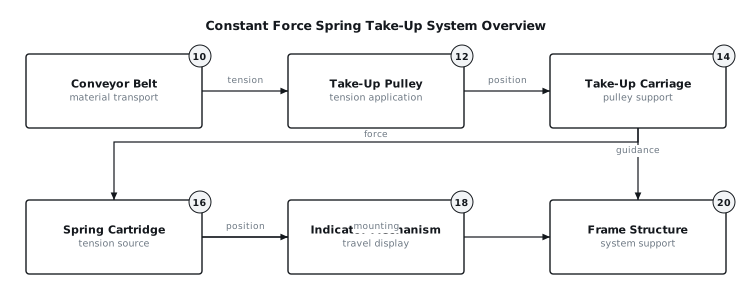
[0001]The present disclosure relates to conveyor systems, and more particularly to mechanisms for maintaining tension in conveyor belts. Specifically, it concerns take-up arrangements that provide consistent tension over a range of belt elongation.
2. Technical Context
[0002]Conveyor belts require a specific tension to ensure proper tracking, prevent slippage at drive pulleys, and maintain effective material transport. Traditional methods for managing belt tension include gravity take-up systems and screw take-up systems. Gravity take-ups utilize a counterweight acting on a take-up pulley to apply tension. While effective, they demand significant vertical headroom or a deep pit for the counterweight's travel, which can be a constraint in many industrial environments. Screw take-up systems use threaded rods to manually adjust the position of a take-up pulley. These systems are compact but require periodic manual adjustment and may allow belt tension to drift unnoticed over time due to belt stretch or temperature changes, potentially leading to operational issues such as belt slippage or material spillage. There is a need for a take-up mechanism that is compact, automatically maintains tension, and provides clear indication of its operational status.
3. System Overview
[0003]The disclosed system provides a compact and automatically tensioning take-up for conveyor belts, addressing the limitations of traditional gravity and screw take-up mechanisms. It comprises a take-up carriage (14) supporting a take-up pulley (12), a constant force spring cartridge (16) that applies tension to the take-up carriage (14), and an indicator mechanism (18) to show the remaining travel of the take-up system. The constant force spring cartridge (16) is designed to exert a nearly uniform tension force across its specified range of extension. This force is transmitted to the take-up pulley (12) via the take-up carriage (14), which is guided along a linear path by a frame structure (20). The indicator mechanism (18) is mechanically linked to the take-up carriage (14) or the spring cartridge (16) and provides a visual representation of the available take-up travel, allowing operators to monitor belt elongation and anticipate maintenance requirements. The overall arrangement, as depicted in FIG. 1, integrates these components to provide a self-adjusting tensioning solution.
4. Components
[0004]The system incorporates several key components. A conveyor belt (10) forms the transport medium, requiring tension for proper operation. A take-up pulley (12) engages with the conveyor belt (10) and is movable to adjust belt tension. The take-up pulley (12) is mounted within a take-up carriage (14). This carriage (14) is designed to slide along a defined linear path, typically guided by linear guides (22) or rollers integrated into the frame structure (20).
[0005]The primary tensioning element is the constant force spring cartridge (16). This cartridge contains one or more coiled springs, often made of pre-stressed flat strip material, that are designed to uncoil or coil with a near-constant force output over a substantial portion of their travel. The cartridge (16) is mechanically coupled to the take-up carriage (14) via a tensioning cable, chain, or direct mechanical linkage. It is typically mounted to the stationary frame structure (20).
[0006]An indicator mechanism (18) provides visual feedback on the take-up system's position and remaining travel. This can be a simple rod with markings, a pointer on a scale, or a rotary encoder linked to the carriage's movement. The indicator (18) is typically fixed to the frame (20) with a movable element attached to the carriage (14) or to the spring cartridge's (16) output shaft.
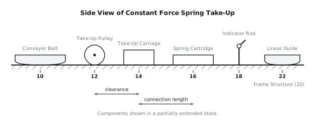
[0007]The frame structure (20) provides the rigid support for all components, defining the path of travel for the take-up carriage (14) and providing mounting points for the constant force spring cartridge (16) and the indicator mechanism (18). Limit switches (24) may also be incorporated at the extreme ends of the take-up carriage's (14) travel to signal maximum extension or retraction. FIG. 2 illustrates an elevation view of these components.
5. Operation
[0008]The operation of the constant force spring take-up system is largely automatic, maintaining belt tension through its inherent design.
[0009]At start-up or during initial belt installation, the conveyor belt (10) is threaded onto the pulleys, including the take-up pulley (12). The take-up carriage (14) is then adjusted, either manually or by its own spring force, to a position within the operating range of the constant force spring cartridge (16). This initial positioning sets the desired tension in the belt (10). The indicator mechanism (18) will show the current position relative to the full available travel.
[0010]During steady running, the constant force spring cartridge (16) continuously applies a substantially constant force to the take-up carriage (14), thereby maintaining the specified tension in the conveyor belt (10). As the conveyor belt (10) stretches due to operational loads, temperature changes, or material creep, the constant force spring cartridge (16) automatically extends, allowing the take-up carriage (14) to move further along its linear guides (22). This movement compensates for the increased belt length, ensuring that the tension remains within the desired operating range. The indicator mechanism (18) dynamically updates, showing the gradual consumption of available take-up travel as the belt (10) elongates.
[0011]In the event of a belt stretch event, such as a sudden increase in load or during the initial break-in period of a new belt, the belt (10) may elongate more rapidly. The constant force spring cartridge (16) responds by extending further, allowing the take-up pulley (12) to move to a new position that accommodates the increased belt length while maintaining the pre-set tension. The indicator mechanism (18) will reflect this increased extension. Should the take-up carriage (14) approach its maximum extension limit, an optional limit switch (24) can be triggered, providing an alert that the belt (10) requires shortening or replacement.
[0012]On fault or interruption, such as a belt break, the tension in the belt (10) is suddenly released. The constant force spring cartridge (16) will retract the take-up carriage (14) to its minimum extension position. An optional limit switch (24) at the fully retracted position can be used to signal this condition, potentially initiating an emergency stop of the conveyor system. Conversely, if the take-up carriage (14) reaches its hard stop at maximum extension, indicating that the belt (10) has stretched beyond the system's compensation capability, another limit switch (24) can trigger a warning or shutdown.
6. Example Embodiments
[0013]Embodiment 1 In this configuration, the constant force spring cartridge (16) is mounted directly to the frame structure (20) at one end, and its extending element, often a cable or strap, is routed over a small idler pulley and attached to the take-up carriage (14). The indicator mechanism (18) comprises a graduated rod fixed to the frame (20) parallel to the direction of carriage travel, with a pointer attached to the take-up carriage (14). The rod has markings indicating percentage of travel used or remaining, and distinct colored bands for operational, warning, and critical zones. The carriage (14) moves on linear ball bearings running on hardened steel shafts, providing low friction movement.
[0014]Embodiment 2 This embodiment utilizes two constant force spring cartridges (16) mounted in parallel, symmetrically positioned on either side of the take-up carriage (14). This arrangement distributes the tensioning load and can provide a higher overall tension force or redundancy. Each cartridge's output is connected to the take-up carriage (14) via a short chain. The indicator mechanism (18) employs a rack and pinion system. A rack is fixed to the frame (20), and a pinion gear, integrated with a rotary dial indicator, is mounted on the take-up carriage (14). As the carriage (14) moves, the pinion rotates the dial, which is marked with travel distances. The take-up carriage (14) runs on self-lubricating polymer slide bearings within a channel section of the frame (20).
[0015]Embodiment 3 In this configuration, the constant force spring cartridge (16) is enclosed within a protective housing that is integral to the frame structure (20). The extending element of the spring is a rigid rod that directly pushes or pulls the take-up carriage (14). The indicator mechanism (18) is a flag or marker attached to this rigid rod, which protrudes through a slot in the housing, moving along a printed scale on the housing exterior. This provides a robust, protected system suitable for environments with high dust or debris. The take-up carriage (14) is guided by precision ground rollers running on inverted angle iron tracks.
7. Alternative Configurations
[0016]The constant force spring cartridge (16) may be replaced by an array of coil springs configured to provide a composite force characteristic that approximates a constant force over the required travel, potentially using a cam mechanism to linearize the force. Alternatively, a pneumatic cylinder system employing a pressure regulator can be used to provide a near-constant force, though this requires an external air supply. The connection between the spring cartridge (16) and the take-up carriage (14) could be a direct push rod, a high-strength strap, or a wire rope pulley system to multiply the spring's force or change its direction. The linear guides (22) for the take-up carriage (14) could be V-groove wheels running on rails, plain bearing slides, or even simple low-friction polymer pads sliding on a polished surface. The indicator mechanism (18) could incorporate an inductive sensor or a linear potentiometer to provide an electrical signal for remote monitoring of take-up position, in addition to or in place of the local visual indicator.
8. Parameter Variations
| Parameter | Range | Effect of Increasing Value | Effect of Decreasing Value |
|---|---|---|---|
| Spring Cartridge Force | 500 N to 10,000 N | Higher belt tension, reduced slip risk, higher component stress | Lower belt tension, increased slip risk, reduced component stress |
| Spring Cartridge Travel | 100 mm to 1,500 mm | Accommodates greater belt elongation, longer belt life | Accommodates less belt elongation, more frequent belt maintenance |
| Take-Up Carriage Mass | 10 kg to 500 kg | Increased inertia, slower response to belt changes | Reduced inertia, faster response to belt changes |
| Linear Guide Friction | 0.01 to 0.1 (coefficient) | Higher hysteresis, less precise tension control | Lower hysteresis, more precise tension control |
| Indicator Resolution | 1 mm to 10 mm per division | More precise status monitoring, more detailed maintenance planning | Less precise status monitoring, broader maintenance windows |
| Belt Length | 5 m to 500 m (center-to-center) | Requires greater take-up travel due to elongation | Requires less take-up travel |
9. Additional Implementations
[0018]This constant force spring take-up system can be integrated into various types of belt conveyors beyond standard troughing conveyors, such as flat belt conveyors, cleated belt conveyors, and even certain types of bucket elevators where a continuous belt is used. The principle can be adapted for tensioning other linear flexible elements like cables in hoist systems or chains in power transmission applications, provided the constant force characteristic is suitable for the specific application. For very long conveyors where total expected belt elongation exceeds the practical travel of a single constant force spring cartridge, multiple cartridges can be arranged in a staged or parallel configuration, or the system can be combined with a secondary, less frequently adjusted coarse take-up mechanism. The travel indication can be augmented with a data logging system, recording the rate of belt elongation over time, which can provide predictive maintenance insights regarding belt lifespan or operational changes. The entire take-up assembly can be mounted on a pivoted arm to allow for angular adjustment in addition to linear translation, useful for maintaining belt alignment in certain specialized conveyor geometries.
10. Figures