Abstract
This disclosure describes a right-angle article transfer system designed to correct article skew during redirection. The system utilizes a lift-and-shift roller bank to receive articles from an input conveyor, elevate them, square them against a reference surface, and then transfer them onto an output conveyor moving at a right angle. This arrangement prevents the propagation of article misalignment, which can lead to downstream processing issues, jamming, or quality control problems. The design accounts for article stability during the lift and accommodates articles that exceed the squaring mechanism's length capacity.
1. Technical Field
[0001]This disclosure relates to automated material handling and conveyor systems, specifically concerning mechanisms for reorienting articles during transfer between orthogonal conveyor paths. The focus is on processes that ensure articles are correctly aligned for subsequent operations, mitigating issues arising from article skew.
2. Technical Context
[0002]In many automated production and logistics environments, articles are transported by conveyors and frequently require changes in direction. A common change is a 90-degree turn from one conveyor line to another. Simple right-angle transfers, such as those employing pop-up roller or chain transfers, often maintain the existing orientation of an article relative to its direction of travel. If an article arrives at the transfer point skewed relative to the input conveyor's direction, it will typically transfer onto the output conveyor with that same skew. This can lead to articles accumulating further skew as they proceed downstream, potentially causing jams, misfeeds into processing equipment, or improper presentation for scanning, labeling, or packaging. A mechanism is therefore required to correct this skew during the transfer process itself.
3. System Overview
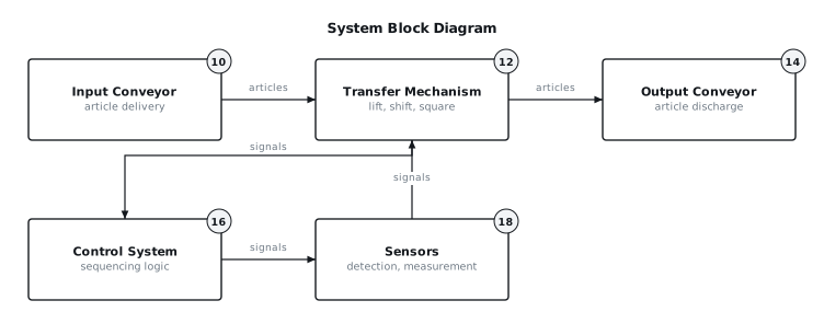
[0003]The described system provides a mechanism for transferring articles at a right angle while simultaneously correcting any angular misalignment. As depicted in the block diagram of FIG. 1, articles are delivered to the transfer mechanism (12) by an input conveyor (10). The transfer mechanism (12) employs a series of liftable rollers that, when raised, elevate the article clear of the input conveyor (10) and subsequently the output conveyor (14). While elevated, the article is driven by the lift rollers and guided against a fixed squaring stop, thereby aligning its leading edge perpendicular to the output conveyor's direction of travel. Once squared, the article is lowered onto the output conveyor (14) for continued transport. A control system (16), informed by various sensors (18), orchestrates the timing and sequence of these operations.
4. Components
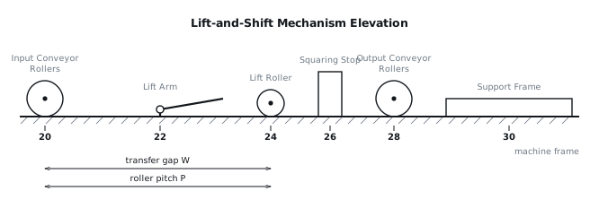
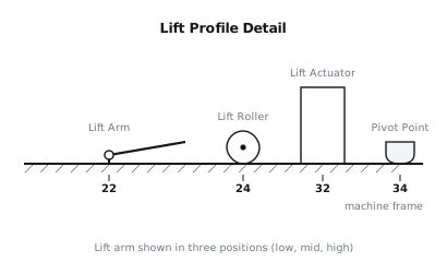
[0004]The core of the system consists of a transfer frame (30) positioned between an input conveyor (20) and an output conveyor (28), as shown in FIG. 2. The input conveyor (20) and output conveyor (28) typically consist of multiple driven rollers or a belt. The transfer frame (30) supports an array of lift arms (22), each equipped with one or more lift rollers (24). These lift rollers (24) are driven, for example, by a continuous belt or chain passing beneath them, or by individual motors. The lift arms (22) are connected to a lift mechanism, which can be actuated by an electric motor, pneumatic cylinders, or a cam system (32), as illustrated in FIG. 3. The lift mechanism raises and lowers the lift arms (22) and their associated lift rollers (24).
[0005]Adjacent to the path of the lift rollers (24) is a squaring stop (26). This squaring stop (26) is typically a rigid, low-friction surface, such as a polished steel plate or a high-density polyethylene guide, mounted parallel to the desired direction of travel of the output conveyor (28). Sensors (18) are strategically placed along the input conveyor (10) and within the transfer mechanism (12). These include article presence sensors (e.g., photo-eyes or proximity sensors) and, in some configurations, article length measurement sensors (e.g., arrays of photo-eyes or laser distance sensors). A control system (16), such as a programmable logic controller (PLC), manages the timing and coordination of the lift mechanism (32), the lift roller drive, and the input and output conveyors (20, 28).
5. Operation
[0006]The operation begins with an article (A) approaching the transfer mechanism (12) on the input conveyor (10). A leading edge sensor (18) detects the arrival of article (A). The control system (16) registers this detection and monitors the article's progress. As article (A) passes over the transfer frame (30), the input conveyor (10) may continue to operate or temporarily stop, depending on the system design and article density.
[0007]Once article (A) is fully positioned over the lift rollers (24), or when its trailing edge clears a specific point, the lift mechanism (32) is actuated. The lift arms (22) raise the lift rollers (24) through the gaps between the input conveyor rollers (20) and then through the gaps between the output conveyor rollers (28), elevating article (A) clear of both conveyors. The lift profile, as shown in FIG. 3, is often a multi-stage process: an initial rapid rise to engage the article, followed by a slower, controlled rise to the full transfer height. This controlled ascent minimizes the risk of tipping tall or unstable articles. The lift rollers (24) begin rotating simultaneously or immediately after initial engagement, driving article (A) sideways towards the squaring stop (26).
[0008]Article (A) slides along the rotating lift rollers (24) until its leading edge (relative to the output conveyor direction) contacts the squaring stop (26). The lift rollers (24) continue to drive, causing article (A) to rotate until its side is fully parallel with the squaring stop (26). This frictional contact and rotation corrects any skew. Once squared, a sensor may confirm the article's position, or a timed interval may be used.
[0009]After squaring, the lift mechanism (32) lowers the lift rollers (24), depositing article (A) onto the output conveyor (28). The output conveyor (28) then transports article (A) away. The lowering profile is typically the reverse of the lifting profile, with a controlled descent to prevent impacts. The lift mechanism (32) then returns to its home position, ready to receive the next article. The entire cycle, from article detection to discharge onto the output conveyor, defines the timing window for the transfer. For articles that are too long to square, meaning their length along the squaring stop exceeds the lateral dimension of the lift roller bank, the article may still be driven into contact with the squaring stop. However, the portions of the article extending beyond the squaring stop will not be actively squared and may retain some skew. The central portion of such an article will be squared, providing partial correction.
6. Example Embodiments
[0010]Embodiment 1 This embodiment features a pneumatically actuated lift mechanism. Each lift arm (22) is directly connected to a small pneumatic cylinder (32). A single air manifold supplies pressure to all cylinders simultaneously, ensuring synchronous lifting. The lift rollers (24) are driven by a single continuous flat belt that runs beneath all the rollers and is powered by a central motor (24). The squaring stop (26) is a fixed, non-adjustable guide rail constructed from ultra-high-molecular-weight polyethylene (UHMW-PE). Article presence and squaring completion are detected by an array of three photo-eyes (18) positioned across the transfer width.
[0011]Embodiment 2 This embodiment employs a cam-driven lift mechanism. A rotating cam shaft, powered by a servo motor (32), engages followers on each lift arm (22), providing a precisely controlled lift and lower profile. The lift rollers (24) are individually driven by small DC motors with integrated gearboxes, allowing for variable speed control and independent rotation for specialized article handling. The squaring stop (26) is constructed from stainless steel and is equipped with a linear actuator for motorized adjustment of its position, allowing for rapid changeovers between different article widths. Article length is measured by a laser scanner (18) on the input conveyor (10) before the article reaches the transfer point.
[0012]Embodiment 3 In this embodiment, the lift mechanism uses a scissor-lift arrangement actuated by a single electric screw jack (32). This provides a robust and precise vertical motion. The lift rollers (24) are passive (non-driven) and instead, the entire lift assembly is mounted on linear bearings and is shifted sideways by a pneumatic cylinder (22) to contact the squaring stop (26). Once contacted, the article is then transferred by an auxiliary belt conveyor integrated into the lift platform, running perpendicular to the input conveyor (10). The squaring stop (26) is a flexible brush-type guide, suitable for delicate articles, mounted on a spring-loaded pivot to absorb impact.
7. Alternative Configurations
[0013]Instead of lift rollers (24), the transfer mechanism (12) could employ lift chains or lift belts. These would raise the article and convey it, potentially eliminating the need for separate squaring stops if the chains/belts are arranged to guide the article. The squaring stop (26) could be retractable or articulated, moving out of the way for articles that do not require squaring or for maintenance access. The drive for the lift rollers (24) could be a series of individual motors, or a single motor driving a common shaft with gears or sprockets for each roller. The lift mechanism (32) could be a hydraulic cylinder system, especially for heavier articles. The input and output conveyors (10, 14) do not necessarily have to be roller conveyors; they could be belt conveyors, slat conveyors, or chain conveyors, provided the lift mechanism can safely pass through their conveying surface.
8. Parameter Variations
| Parameter | Realistic Range | Effect of Increase | Effect of Decrease |
|---|---|---|---|
| Lift Height | 5 to 50 mm above conveyor surface | Accommodates taller conveyor components, reduces risk of dragging, requires longer lift stroke. | Risks article dragging on conveyor components, shorter lift stroke, faster cycle time. |
| Lift Speed | 0.1 to 1.5 m/s | Faster cycle time, increased dynamic forces, higher power requirement for lift actuator, potential for article instability. | Slower cycle time, reduced dynamic forces, lower power requirement, improved article stability. |
| Lift Roller Speed | 0.5 to 3.0 m/s | Faster squaring action, increased friction wear on squaring stop, higher power for roller drive, potential for article spin. | Slower squaring action, longer squaring time, reduced friction wear, gentler article handling. |
| Squaring Stop Clearance | 0 to 5 mm | Provides tolerance for article width variations, reduces friction, may result in slight residual skew if too large. | Requires precise article width, increases friction, potential for jamming if too tight. |
| Article Weight | 0.1 to 50 kg | Requires more robust lift mechanism and frame, higher actuator power, slower lift speeds for stability. | Allows for lighter construction, faster lift speeds, less powerful actuators. |
| Article Length | 100 to 1500 mm | Longer articles may exceed squaring stop length, requiring alternative squaring strategies or partial squaring. Longer transfer time. | Shorter articles are easier to square, faster transfer time, reduced risk of overhang. |
| Roller Pitch (P) | 40 to 200 mm | Fewer rollers, larger gaps, potential for small articles to fall or sag. | More rollers, smaller gaps, better support for small articles, increased system complexity and cost. |
9. Additional Implementations
[0015]The described lift-and-shift squaring mechanism can be integrated into a larger material flow system. For instance, it can be combined with vision systems (18) for quality inspection or orientation verification immediately after squaring. It can also be configured as a buffering station, where articles are held on the raised rollers before being released onto the output conveyor (14) based on downstream demand. For articles that are sensitive to lateral force, the squaring stop (26) could be replaced by a series of movable guides that gently close in on the article to achieve squaring, rather than relying on direct impact. The system can be designed with a variable-angle squaring stop, allowing articles to be oriented at angles other than precisely 90 degrees relative to the output conveyor. Furthermore, the lift rollers (24) could be reversible, allowing for bi-directional transfer or back-feeding of articles in specific fault conditions.
10. Figures