Abstract
This disclosure describes a system for anti-sway control in crane operations, addressing the challenge of load oscillation caused by varying rope lengths. The system utilizes real-time measurements of rope angle and length to dynamically generate an acceleration and deceleration profile for the crane's load-carrying mechanism. This profile is continuously adjusted to match the natural period of oscillation of the suspended load, minimizing sway during and after load movement. The approach ensures effective sway reduction across the full range of operational rope lengths, improving stability and operational precision without relying on fixed tuning parameters.
1. Technical Field
[0001]The present disclosure relates to industrial hoisting and material handling equipment, specifically to systems designed for the control of suspended loads to mitigate unwanted oscillatory motion during and after translation.
2. Technical Context
[0002]The movement of a suspended load by a crane or hoist introduces a pendulum-like oscillation, commonly referred to as sway. This sway is a significant challenge in crane operations, potentially leading to reduced operational speed, decreased safety, and imprecise load placement. Traditional anti-sway control methods often rely on open-loop acceleration and deceleration profiles designed to counteract the natural period of the pendulum. However, the natural period of a simple pendulum is directly dependent on its length. In crane applications, the rope length (and thus the pendulum length) can vary significantly during hoisting or lowering operations, or between different lifting tasks. An open-loop anti-sway profile tuned for a single, fixed rope length becomes ineffective, or even counterproductive, at other rope lengths, resulting in excessive residual sway. There is a need for a dynamic control approach that adapts to the continuously changing rope length to maintain effective sway suppression throughout the operational envelope.
3. System Overview
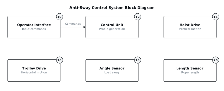
[0003]The described system provides dynamic anti-sway control for cranes by adjusting the acceleration and deceleration profiles of the hoist and trolley drives based on real-time feedback of the load's sway angle and the effective rope length. As illustrated in the block diagram of FIG. 1, an operator interface (10) provides target movement commands to a control unit (12). The control unit (12) receives continuous data regarding the load's angular displacement from an angle sensor (18) and the current effective rope length from a length sensor (20). Using these inputs, the control unit (12) calculates and implements an optimized acceleration and deceleration profile that directly drives the hoist drive (14) and trolley drive (16). This dynamic profile generation ensures that the acceleration and deceleration phases are precisely tailored to the instantaneous pendulum characteristics, effectively damping load sway throughout the entire travel path and minimizing residual oscillation upon reaching the target position.
4. Components
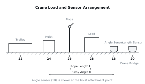
[0004]The system comprises several key components, as depicted in FIG. 1 and FIG. 2:
[0005]
- Operator Interface (10): This unit allows an operator to input desired movement commands, such as target horizontal position, vertical position, and desired travel speed. It typically includes joysticks, push buttons, or a touchscreen display.
- Control Unit (12): This is the central processing element of the system. It consists of a programmable logic controller (PLC), an industrial PC, or a dedicated embedded controller. The control unit (12) executes the anti-sway algorithms, processes sensor data, calculates the dynamic acceleration profiles, and generates control signals for the drive systems. It includes input interfaces for sensors and output interfaces for drive commands.
- Hoist Drive (14): This component controls the vertical movement of the load. It typically includes a motor, a gearbox, a drum for the rope, and a variable frequency drive (VFD) or servo drive for precise speed and acceleration control.
- Trolley Drive (16): This component controls the horizontal movement of the load along the crane bridge. It typically includes a motor, a gearbox, wheels for trolley translation, and a variable frequency drive (VFD) or servo drive for precise speed and acceleration control.
- Angle Sensor (18): This sensor measures the angular displacement of the rope (26) from the vertical axis. It is typically a non-contact sensor, such as an optical sensor, a laser displacement sensor, or a vision-based system, mounted at or near the hoist attachment point to the trolley (22), as shown in FIG. 2. It provides real-time feedback on the load's (28) sway angle.
- Length Sensor (20): This sensor measures the effective length of the rope (26) from its suspension point on the hoist (24) to the load (28). This can be achieved using an encoder on the hoist drum, a laser distance sensor aimed at the load, or a similar method providing continuous length data.
5. Operation
[0006]The anti-sway control system operates through a continuous feedback loop and dynamic profile generation:
[0007]Start-Up and Initialization: Upon system power-on, the control unit (12) performs self-diagnostics and initializes all sensors and drives. The length sensor (20) provides an initial rope length (L) measurement. The angle sensor (18) provides initial angular displacement (θ) data, which should ideally be zero if the load (28) is stationary and centered. The control unit (12) then enters a ready state, awaiting operator commands.
[0008]During Steady Running (Acceleration/Deceleration): When the operator inputs a movement command via the operator interface (10), the control unit (12) begins to generate a dynamic acceleration profile. The fundamental principle is to match the acceleration and deceleration phases of the trolley (22) movement to the natural period of oscillation of the suspended load (28). The natural period (T) of a simple pendulum is approximated by the formula T = 2π√(L/g), where L is the rope length and g is the acceleration due to gravity.
[0009]The length sensor (20) continuously transmits the current rope length (L) to the control unit (12) at a refresh rate of typically 10 to 100 Hz. The control unit (12) calculates the corresponding natural period T. It then computes an acceleration profile that applies an initial impulse to start the load (28) moving, followed by a period where the trolley (22) accelerates in phase with the load's (28) pendulum swing. Similarly, the deceleration profile is shaped to bring the trolley (22) to a stop in a manner that naturally dampens any induced sway. This involves reducing trolley speed such that the load (28) swings forward, and the trolley (22) reaches its target position as the load (28) returns to its vertical, stationary state.
[0010]The angle sensor (18) provides real-time feedback on the actual sway angle (θ). This feedback is used by the control unit (12) for closed-loop refinement of the profile. If the measured sway deviates from the predicted or desired minimal sway, the control unit (12) applies minor corrective acceleration or deceleration adjustments to the trolley drive (16) to re-align the trolley (22) motion with the load's (28) swing. These adjustments are typically small and are superimposed on the primary acceleration profile.
[0011]On Fault or Interruption (Operator Override): If the operator overrides the automatic profile mid-move, for example, by directly manipulating a joystick to stop or change direction, the control unit (12) immediately detects this input. In such a scenario, the dynamically generated acceleration profile is suspended. The control unit (12) transitions to a modified deceleration sequence. Instead of simply stopping abruptly, which would induce significant sway, it attempts to bring the trolley (22) to a controlled stop using a rapid but still sway-mitigating deceleration curve, informed by the current rope length (L) and measured sway angle (θ). This "emergency" deceleration is designed to minimize the resulting residual sway as much as possible under the circumstances of an unpredicted interruption, prioritizing safety and stability over perfect sway suppression. The residual sway at stop in such a case will generally be higher than with a fully optimized, uninterrupted profile.
[0012]Residual Sway at Stop: When a movement command is completed without interruption, the control unit (12) executes the deceleration profile. This profile is engineered such that the trolley (22) comes to a full stop precisely at the moment the suspended load (28) completes its final forward swing and returns to the vertical position, with zero horizontal velocity relative to the trolley (22). The objective is to achieve a residual sway angle of less than 0.5 degrees, measured immediately after the trolley (22) has ceased motion. The fine-tuning based on angle sensor (18) feedback during the final phase of deceleration is crucial to achieving this minimal residual sway.
6. Example Embodiments
[0013]Embodiment 1: Single-Axis Horizontal Control In this embodiment, the system primarily focuses on controlling sway during horizontal (trolley) movement. The hoist drive (14) operates independently or with a much slower, non-anti-sway profile. The control unit (12) receives rope length (L) from the length sensor (20) and angle (θ) from the angle sensor (18). It calculates the natural period T and generates an acceleration and deceleration profile specifically for the trolley drive (16). The profile for the trolley drive (16) includes a primary acceleration phase, a constant velocity phase, and a primary deceleration phase. Each phase is shaped with cubic or quintic splines to ensure smooth transitions and reduce jerk. Small corrective inputs to the trolley drive (16) are continuously applied based on the angle (θ) feedback to actively damp any initial or induced sway.
[0014]Embodiment 2: Coordinated Hoist and Trolley Anti-Sway This embodiment extends the control to both horizontal and vertical motion. When the operator initiates a diagonal move (simultaneous hoisting/lowering and trolleying), the control unit (12) generates coupled acceleration profiles for both the hoist drive (14) and the trolley drive (16). The rate of change of rope length (dL/dt) is also factored into the natural period calculation, as changing rope length affects the pendulum's dynamics. The system anticipates the change in natural period as the rope length (L) changes and adjusts both drives' profiles accordingly. For example, if the load (28) is being lowered while trolleying, the natural period increases, and the control unit (12) adapts the trolley's acceleration to accommodate this lengthening pendulum. This coordinated control aims to minimize sway in both horizontal and vertical planes, considering the three-dimensional motion of the load (28).
[0015]Embodiment 3: Predictive Anti-Sway with Path Planning This embodiment integrates advanced path planning with the dynamic acceleration profile. The operator defines a target 3D path for the load (28). The control unit (12) then pre-calculates an optimal movement trajectory, including desired speeds, accelerations, and deceleration points for both hoist (14) and trolley (16), considering the varying rope length (L) along the path. During execution, the angle sensor (18) feedback is used not only for damping but also to detect deviations from the planned path or unexpected external disturbances. The control unit (12) can then make real-time micro-adjustments to the planned trajectory and the acceleration profiles to guide the load (28) back onto the optimal path while maintaining minimal sway. This can involve slightly altering the timing of acceleration or the magnitude of corrective forces.
7. Alternative Configurations
[0016]Various alternative configurations for the system components are possible. The angle sensor (18) could be implemented as a camera-based vision system that tracks features on the load (28) or the rope (26) to determine its angular position. Alternatively, an inertial measurement unit (IMU) with gyroscopes and accelerometers could be mounted directly on the load (28) or its attachment point to measure angular velocity and acceleration, which can then be integrated to determine angle. The length sensor (20) could be a magnetic stripe sensor along the rope path or a sonic sensor measuring distance to the load (28). The control unit (12) logic could be implemented using field-programmable gate arrays (FPGAs) for higher processing speed, especially in systems requiring extremely fast update rates for the acceleration profile. The communication between components could utilize industrial Ethernet protocols, such as EtherCAT or PROFINET, for deterministic and high-speed data exchange.
8. Parameter Variations
| Parameter | Range | Effect of Increasing Value | Effect of Decreasing Value |
|---|---|---|---|
| Rope Length (L) | 2 m to 60 m | Increases natural period, requires longer acceleration/deceleration phases for sway suppression. | Decreases natural period, allows for shorter acceleration/deceleration phases. |
| Load Mass | 100 kg to 50,000 kg | No direct effect on natural period, but requires higher drive torque for same acceleration. | No direct effect on natural period, but reduces required drive torque. |
| Max Trolley Speed | 0.5 m/s to 3.0 m/s | Allows faster material handling if sway is controlled, but demands more precise control. | Limits throughput, but simplifies control due to lower kinetic energy. |
| Angle Sensor Accuracy | ±0.1° to ±1.0° | Enables more precise sway detection and finer corrective adjustments, leading to lower residual sway. | Reduces precision of sway detection, potentially leading to higher residual sway or oscillations. |
| Control Loop Update Rate | 10 Hz to 200 Hz | Provides more frequent profile adjustments and faster response to dynamic changes, improving sway suppression. | Reduces responsiveness to dynamic changes, potentially leading to less effective sway suppression. |
| Maximum Acceleration | 0.1 m/s² to 1.0 m/s² | Shortens travel time but increases demands on drive power and control system stability. | Lengthens travel time but reduces mechanical stress and control complexity. |
9. Additional Implementations
[0018]The described system can be further enhanced or applied in different contexts. One implementation involves integrating wind speed and direction data from an anemometer to compensate for external forces acting on the load (28). The control unit (12) could then adjust the trolley (22) acceleration profile to preemptively counteract wind-induced sway. Another implementation is the integration of collision avoidance sensors, where the anti-sway control system can dynamically modify its acceleration profiles to bring the load (28) to a controlled, sway-minimized stop before a potential collision. The system can also be adapted for gantry cranes or overhead traveling cranes with multiple hoists operating simultaneously, where the control unit (12) would manage coordinated anti-sway movements for several loads, preventing inter-load collisions while minimizing individual load oscillations. Furthermore, the system could be augmented with an operator training mode, where simulated sway conditions are presented via the operator interface (10) to train personnel on optimal control inputs while the anti-sway system actively provides feedback on their performance.
10. Figures