OT-2026-000003154
Tool shaft coupler
- Published
- Permanent URL
- https://opentechnical.org/p/OT-2026-000003154
- Classification
- Industrial Motion & Power Transmission › Rotary Motion
- Assignee
- MEDNEXT INC
- Original source
- US-6062575-A, the United States Patent and Trademark Office, 16 May 2000
- Document SHA-256
- baaf81a7d820f5de43311d3b7f4c560181e37cd505d66392845e8198f30c039a
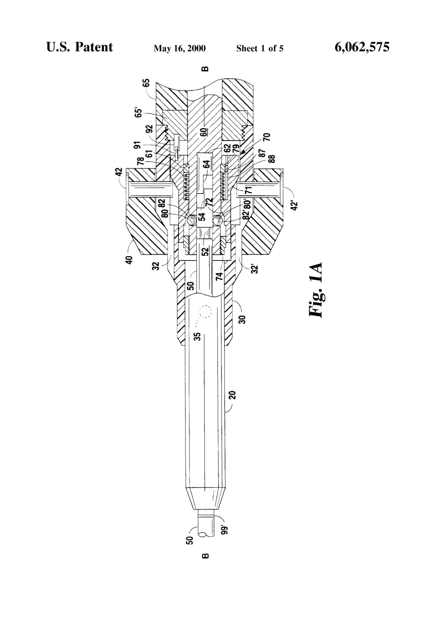
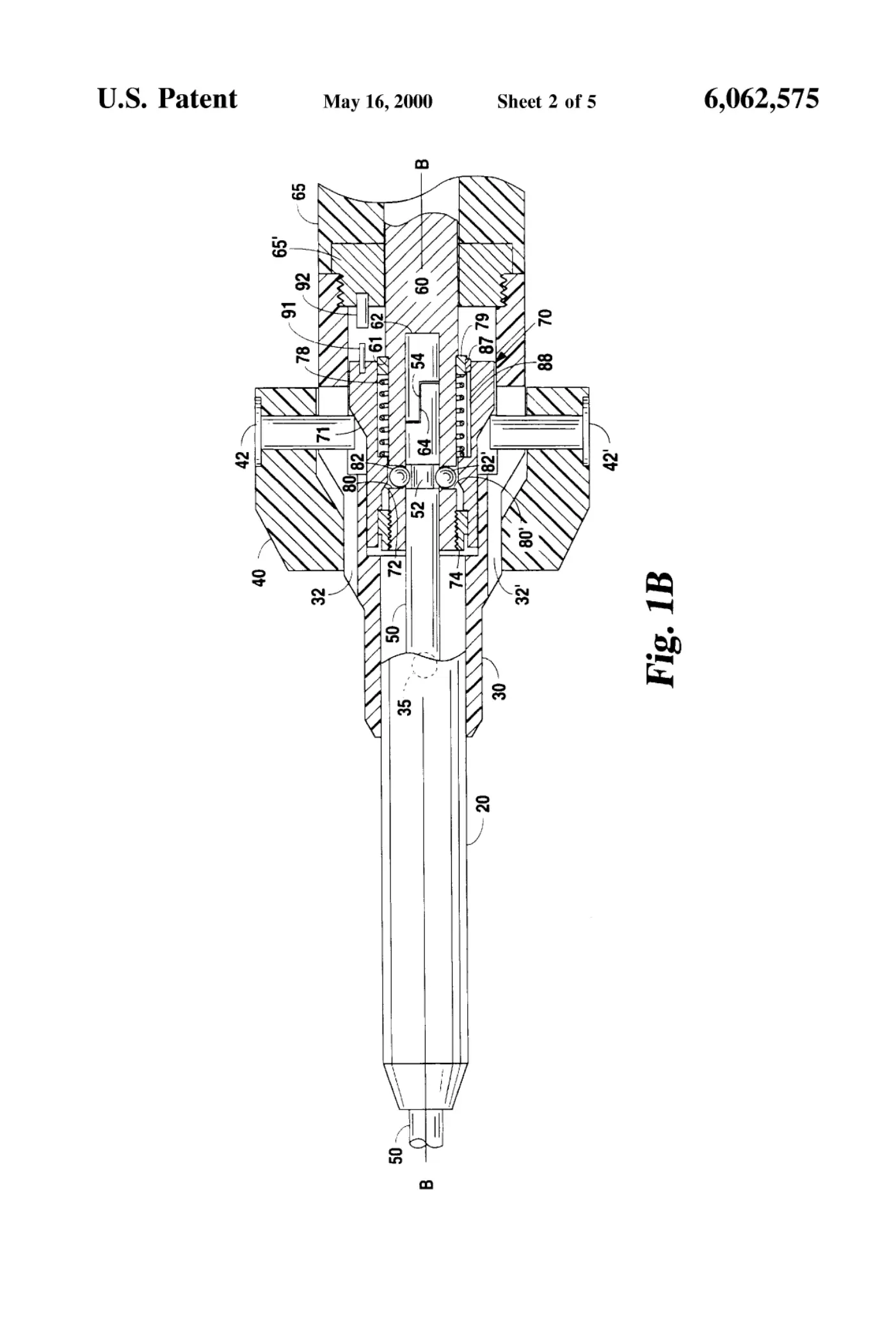
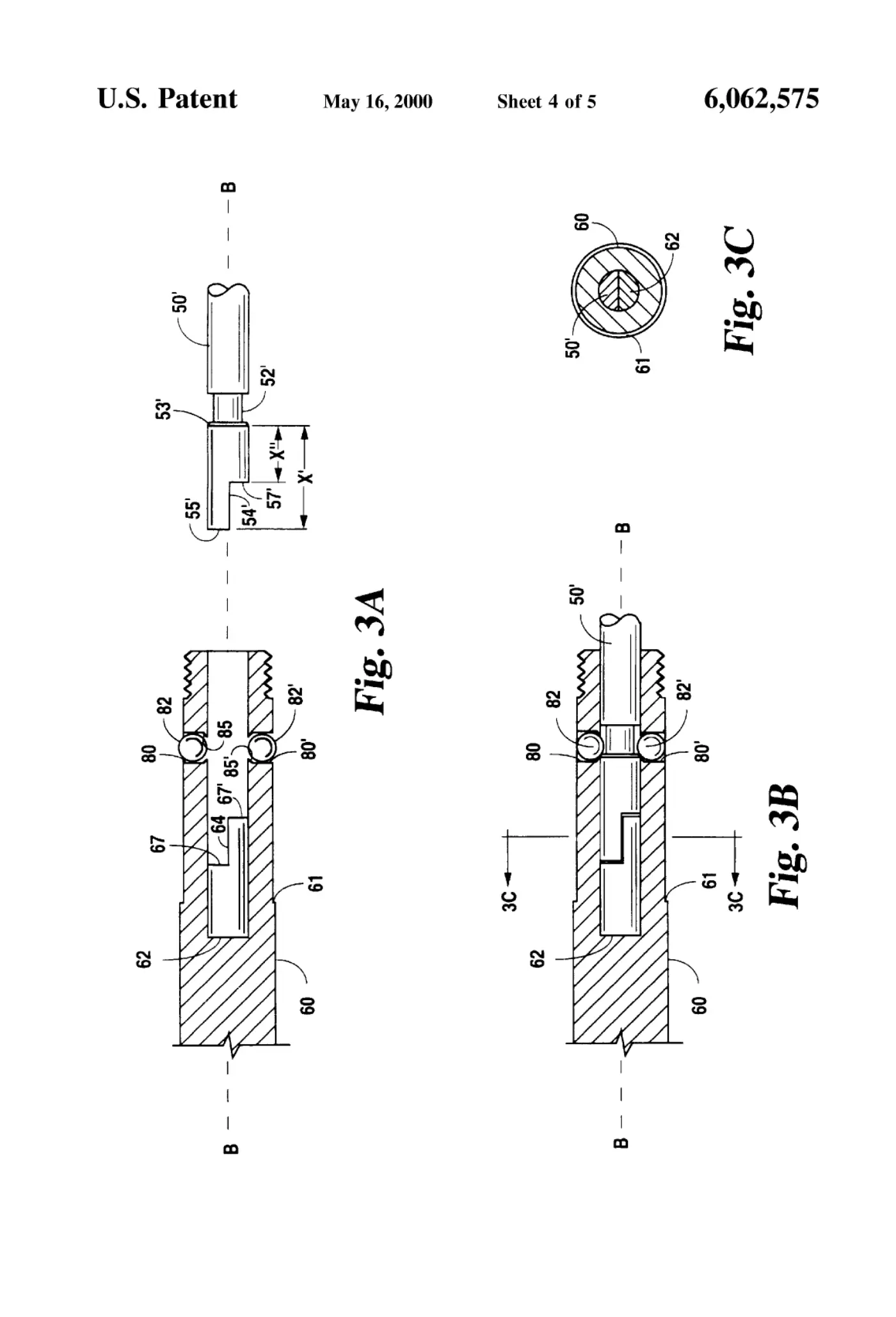
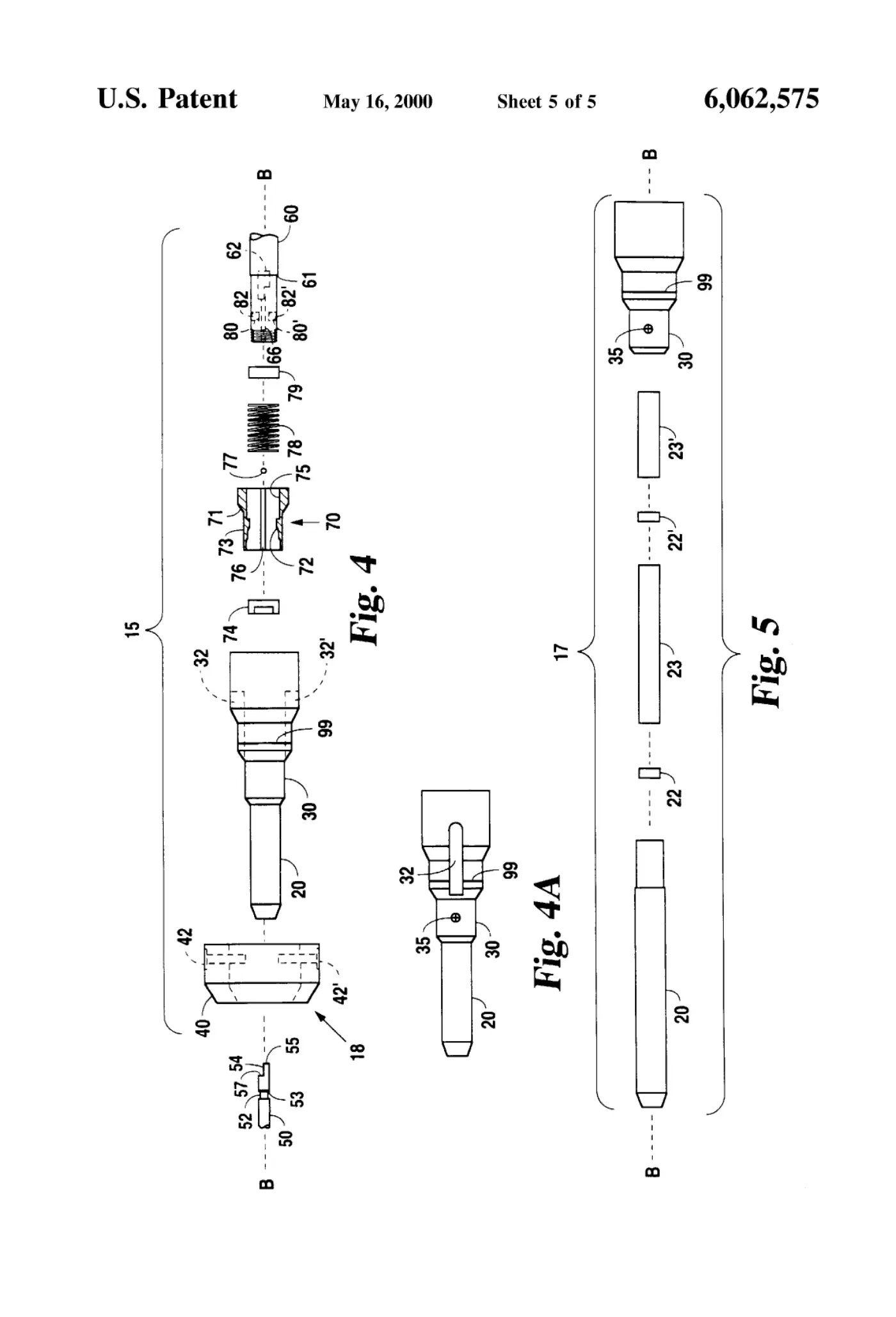
Apparatus and methods for coupling a driving shaft (60) and a mating tool shaft (50, 50') to transmit rotational forces and axial tension and compression between the shafts. The coupler (15) provides for axial tension transmission through tension transmission surfaces (80, 80') spaced-apart from torque (54, 54') and compression (55, 55') transmission surfaces of the mating tool shaft (50, 50'). A separate satefy lock release attachment (17) is preferably removed during tool shaft rotation and can automatically hold the driving shaft (60) stopped when used to release the shaft locking means for a tool change. An optional reversible mechanical interlock (91, 92) further ensures that the driving shaft (60) will remain stopped during a tool change. Malfunction (e.g., improper seating) of the shaft locking means with the attachment ring (70) in place results in a positive visual indication of the malfunction.
Abstract
Apparatus and methods for coupling a driving shaft (60) and a mating tool shaft (50, 50') to transmit rotational forces and axial tension and compression between the shafts. The coupler (15) provides for axial tension transmission through tension transmission surfaces (80, 80') spaced-apart from torque (54, 54') and compression (55, 55') transmission surfaces of the mating tool shaft (50, 50'). A separate satefy lock release attachment (17) is preferably removed during tool shaft rotation and can automatically hold the driving shaft (60) stopped when used to release the shaft locking means for a tool change. An optional reversible mechanical interlock (91, 92) further ensures that the driving shaft (60) will remain stopped during a tool change. Malfunction (e.g., improper seating) of the shaft locking means with the attachment ring (70) in place results in a positive visual indication of the malfunction.
1. Drawings
[0001]Sheet 1.
[0002]Sheet 2.
[0003]Sheet 3.
[0004]Sheet 4.
Publication information
Citation
OpenTechnical Publication OT-2026-000003154, “Tool shaft coupler,” published September 15, 2026 at 19:39:48 UTC, https://opentechnical.org/p/OT-2026-000003154.
To cite specific content, add the paragraph or figure numbers.
Terms
This record reproduces a document published elsewhere and is provided for reference and study. Rights in the original remain with its owner. See the publication policy.