OT-2026-000003169
Pneumatic device
- Published
- Permanent URL
- https://opentechnical.org/p/OT-2026-000003169
- Classification
- Tools & Tooling › Clamping Tools
- Inventors
- TOYODA YUKIHIRO
- Assignee
- MEIHO CO LTD
- Original source
- US-5979213-A, the United States Patent and Trademark Office, 9 November 1999
- Document SHA-256
- db49c4d9d23701fa7b9808e89e93f9cd0c1d329214100e62a75885b2bfebe3de
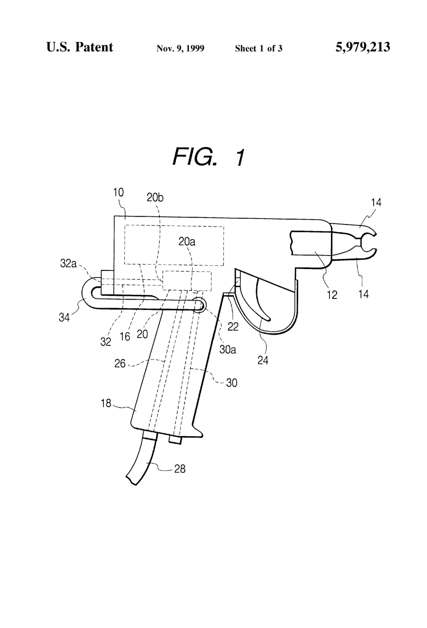
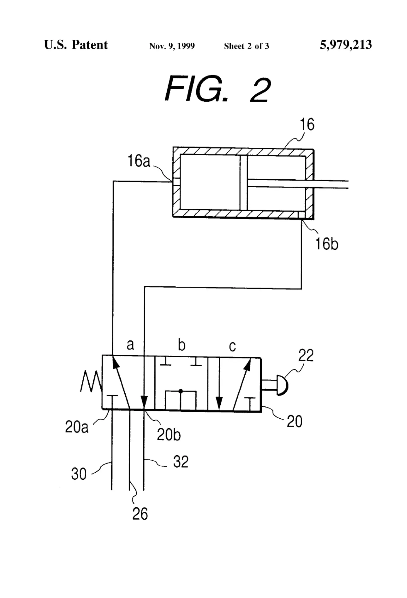
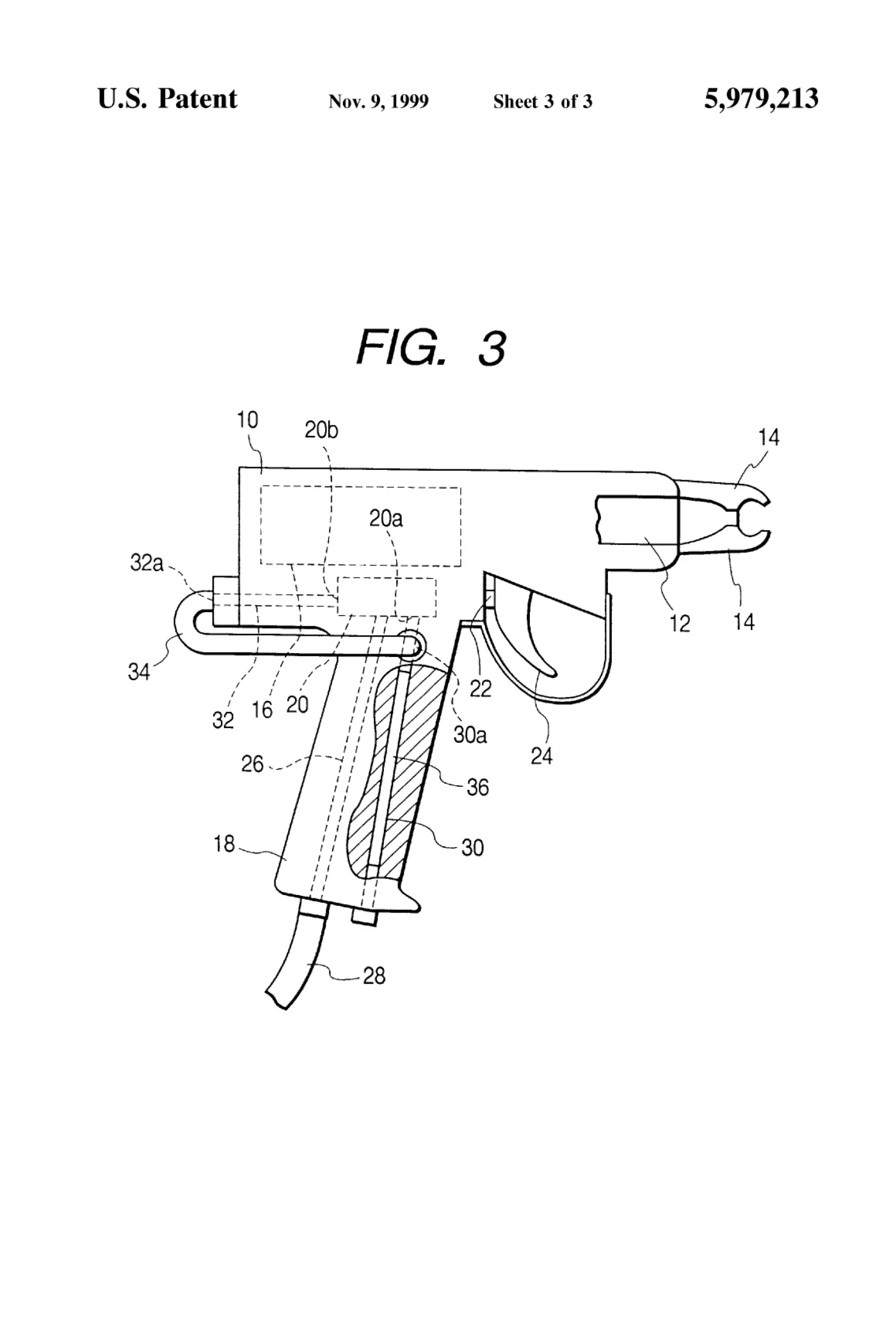
A hand-held pneumatic device, such as a C ring clamping device, comprises a main body, a grip joined to a lower portion of the main body, a pneumatic cylinder contained in the main body, and a directional control valve contained in the main body. A first air discharge passage formed in the grip is connected to a first discharge port of the directional control valve and has an open end in a lower end portion of the grip. A second air discharge passage formed in the main body is connected to a second discharge port of the directional control valve and has an open end opening in a back portion of the main body. The open end of the second air discharge passage is connected to an inner portion of the first air discharge passage, near the first discharge port of the directional control valve, so that air is discharged through the open end of the first air discharge passage.
Abstract
A hand-held pneumatic device, such as a C ring clamping device, comprises a main body, a grip joined to a lower portion of the main body, a pneumatic cylinder contained in the main body, and a directional control valve contained in the main body. A first air discharge passage formed in the grip is connected to a first discharge port of the directional control valve and has an open end in a lower end portion of the grip. A second air discharge passage formed in the main body is connected to a second discharge port of the directional control valve and has an open end opening in a back portion of the main body. The open end of the second air discharge passage is connected to an inner portion of the first air discharge passage, near the first discharge port of the directional control valve, so that air is discharged through the open end of the first air discharge passage.
1. Drawings
[0001]Sheet 1.
[0002]Sheet 2.
[0003]Sheet 3.
Publication information
Citation
OpenTechnical Publication OT-2026-000003169, “Pneumatic device,” published September 15, 2026 at 19:42:50 UTC, https://opentechnical.org/p/OT-2026-000003169.
To cite specific content, add the paragraph or figure numbers.
Terms
This record reproduces a document published elsewhere and is provided for reference and study. Rights in the original remain with its owner. See the publication policy.