OT-2026-000003407
Magnetic chuck
- Published
- Permanent URL
- https://opentechnical.org/p/OT-2026-000003407
- Classification
- Manufacturing & Assembly Equipment › Machining Systems
- Inventors
- ARISHIRO MASATOSHI, NAKAGAWA TADAHIRO, TAZUKE SHIZUMA
- Assignee
- MURATA MANUFACTURING CO
- Original source
- US-5080380-A, the United States Patent and Trademark Office, 14 January 1992
- Document SHA-256
- 9bac88c3a709a304224dc499caace4d413196e8e7af0ecf393756cc89f05ab25
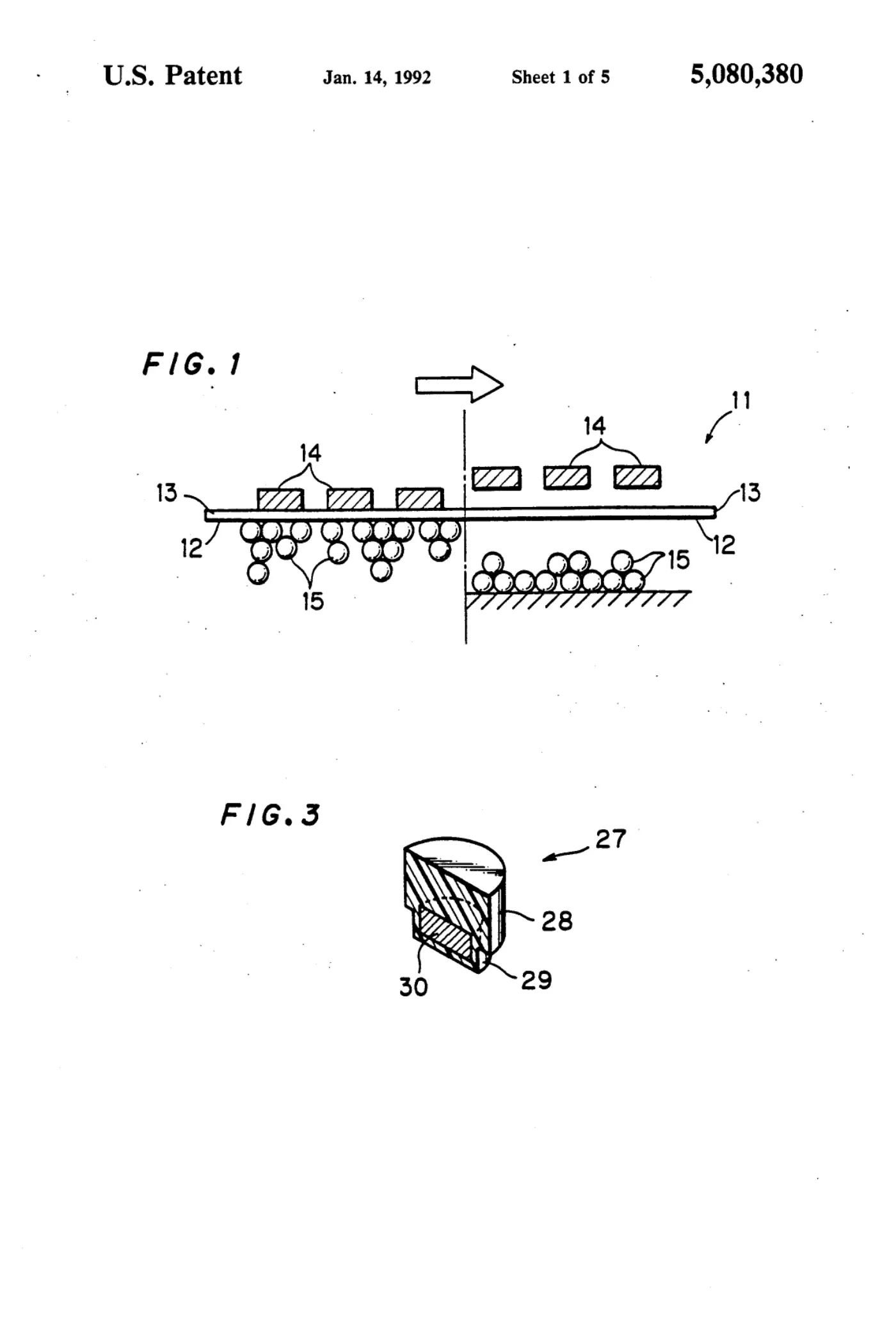
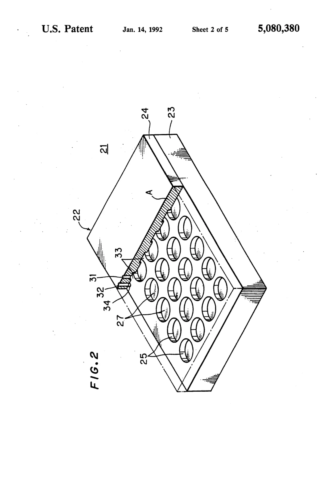
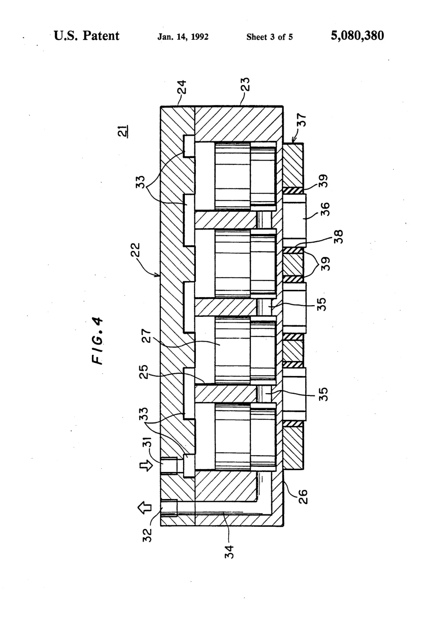
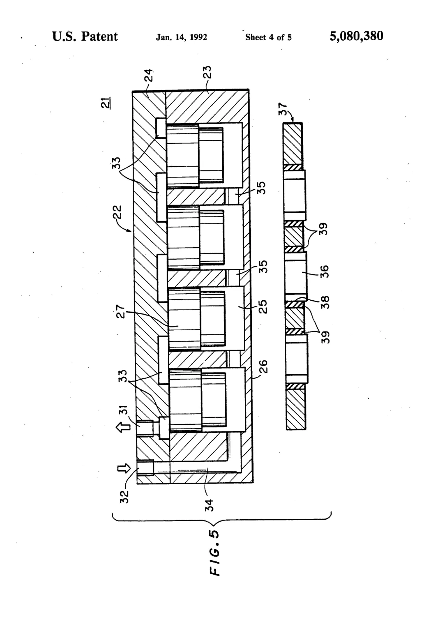
A plurality of vertically extending cylinders are formed in the interior of a chuck body providing a chucking face on its lower surface. Pistons, in which permanent magnets are embedded, are vertically movably provided in respective ones of the cylinders. When compressed air is introduced into upper portions of the cylinders, the pistons are downwardly displaced so that the permanent magnets are relatively approached to the lower surface of the chuck body. Thus, the chucking face is supplied with magnetic force exceeding a prescribed level, to attract a holder holding electronic component chips, for example. When compressed air is introduced into lower portions of the cylinders, on the other hand, the pistons are upwardly displaced so that the permanent magnets are relatively separated from the lower surface of the chuck body. Thus, the chucking face is supplied with no magnetic force exceeding the prescribed level, so that the holder is separated from the chuck body.
Abstract
A plurality of vertically extending cylinders are formed in the interior of a chuck body providing a chucking face on its lower surface. Pistons, in which permanent magnets are embedded, are vertically movably provided in respective ones of the cylinders. When compressed air is introduced into upper portions of the cylinders, the pistons are downwardly displaced so that the permanent magnets are relatively approached to the lower surface of the chuck body. Thus, the chucking face is supplied with magnetic force exceeding a prescribed level, to attract a holder holding electronic component chips, for example. When compressed air is introduced into lower portions of the cylinders, on the other hand, the pistons are upwardly displaced so that the permanent magnets are relatively separated from the lower surface of the chuck body. Thus, the chucking face is supplied with no magnetic force exceeding the prescribed level, so that the holder is separated from the chuck body.
1. Drawings
[0001]Sheet 1.
[0002]Sheet 2.
[0003]Sheet 3.
[0004]Sheet 4.
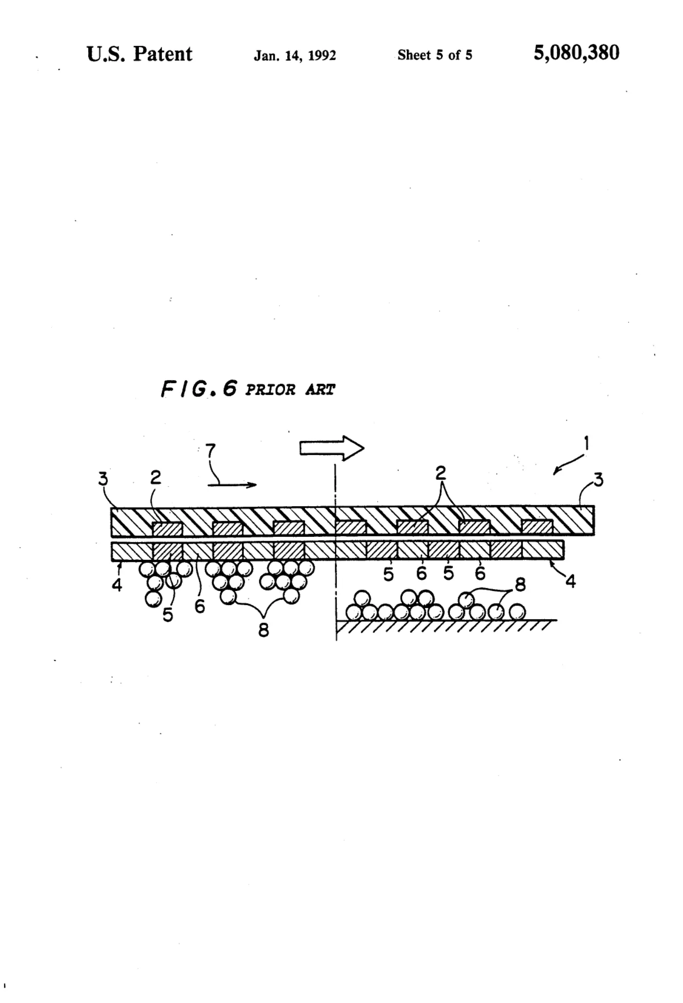
[0005]Sheet 5.
Publication information
Citation
OpenTechnical Publication OT-2026-000003407, “Magnetic chuck,” published September 15, 2026 at 20:23:43 UTC, https://opentechnical.org/p/OT-2026-000003407.
To cite specific content, add the paragraph or figure numbers.
Terms
This record reproduces a document published elsewhere and is provided for reference and study. Rights in the original remain with its owner. See the publication policy.