OT-2026-000003419
Magnetic gripper
- Published
- Permanent URL
- https://opentechnical.org/p/OT-2026-000003419
- Classification
- Lifting, Positioning & Manipulation › Hoists and Cranes
- Inventors
- GEORGIEV ASSEN G, GEORGIEV VALENTIN G, STOEV PLAMEN D, STOJANOV STOJAN D, ZANEV ZANTCHO B
- Assignee
- P S P METALSNAB
- Original source
- US-5038128-A, the United States Patent and Trademark Office, 6 August 1991
- Document SHA-256
- 0297e830f8a8f7476dc021f9eb4c71b3a7a741aaf32e49d052b54172519b20c9
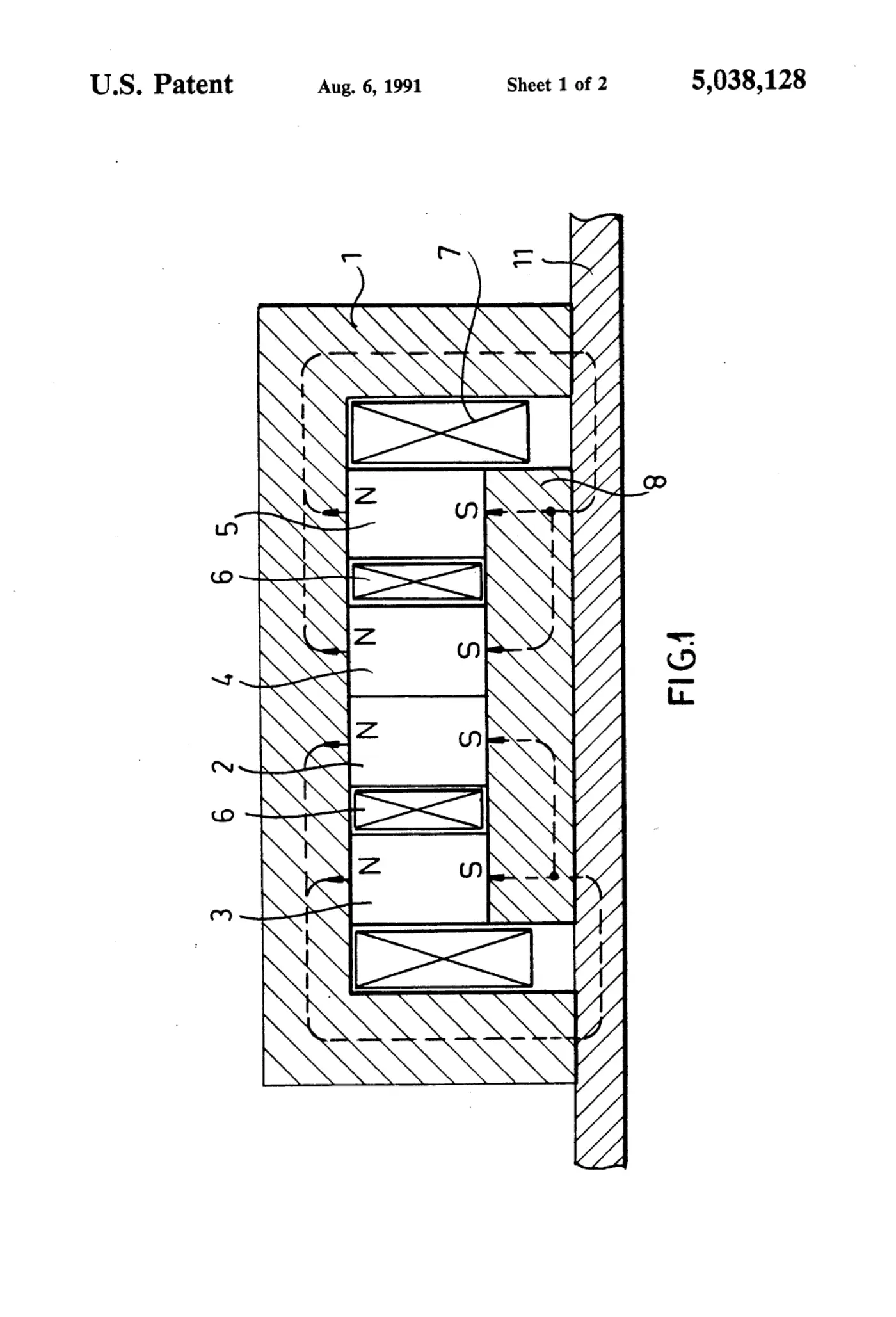
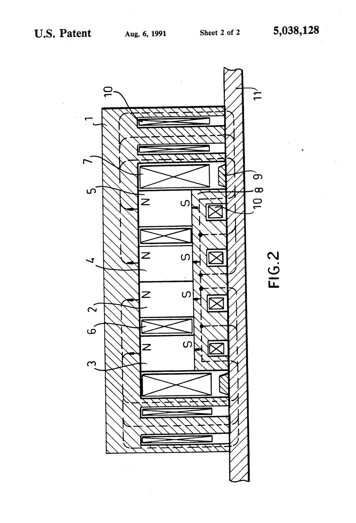
A magnetic gripper avoiding the disadvantages of the well-known devices of reduced lifting capacity, increased electric power consumption and small gripping force finds application in mechanical engineering for the transportation of ferromagnetic materials. The device has a U-shaped casing of magnetic soft material, at least two pairs of permanent magnets, one of their ends resting on the casing and the other on a common pole terminal enveloped in a neutralizing winding and all magnets are enveloped by a magnetizing winding. The magnetic gripper can lift thick sheets and packs of thin sheets when short-time current pulse of the magnetizing winding is fed and the permanent magnets are magnetized in one direction, the magnetic flux formed is collected in the common pole terminal. To free the sheets, a current pulse of the common neutralizing winding is fed and the direction of magnetization is reversed. For the regulation of the gripping force in some sectors of the poles, the magnetic flux is summed and in others is subtracted, thus achieving changes of the gripping force on a wide range with reduced energy consumption.
Abstract
A magnetic gripper avoiding the disadvantages of the well-known devices of reduced lifting capacity, increased electric power consumption and small gripping force finds application in mechanical engineering for the transportation of ferromagnetic materials. The device has a U-shaped casing of magnetic soft material, at least two pairs of permanent magnets, one of their ends resting on the casing and the other on a common pole terminal enveloped in a neutralizing winding and all magnets are enveloped by a magnetizing winding. The magnetic gripper can lift thick sheets and packs of thin sheets when short-time current pulse of the magnetizing winding is fed and the permanent magnets are magnetized in one direction, the magnetic flux formed is collected in the common pole terminal. To free the sheets, a current pulse of the common neutralizing winding is fed and the direction of magnetization is reversed. For the regulation of the gripping force in some sectors of the poles, the magnetic flux is summed and in others is subtracted, thus achieving changes of the gripping force on a wide range with reduced energy consumption.
1. Drawings
[0001]Sheet 1.
[0002]Sheet 2.
Publication information
Citation
OpenTechnical Publication OT-2026-000003419, “Magnetic gripper,” published September 15, 2026 at 20:25:27 UTC, https://opentechnical.org/p/OT-2026-000003419.
To cite specific content, add the paragraph or figure numbers.
Terms
This record reproduces a document published elsewhere and is provided for reference and study. Rights in the original remain with its owner. See the publication policy.