OT-2026-000003424
Conveyor ball unit
- Published
- Permanent URL
- https://opentechnical.org/p/OT-2026-000003424
- Classification
- Industrial Motion & Power Transmission › Rotary Motion
- Inventors
- HUBER THOMAS
- Assignee
- BAVARIA CARGO TECH
- Original source
- US-5033601-A, the United States Patent and Trademark Office, 23 July 1991
- Document SHA-256
- efa5241eb3bfcc82fde7526dcae3aba3c497de3872b1a9391d7203f84b448f7e
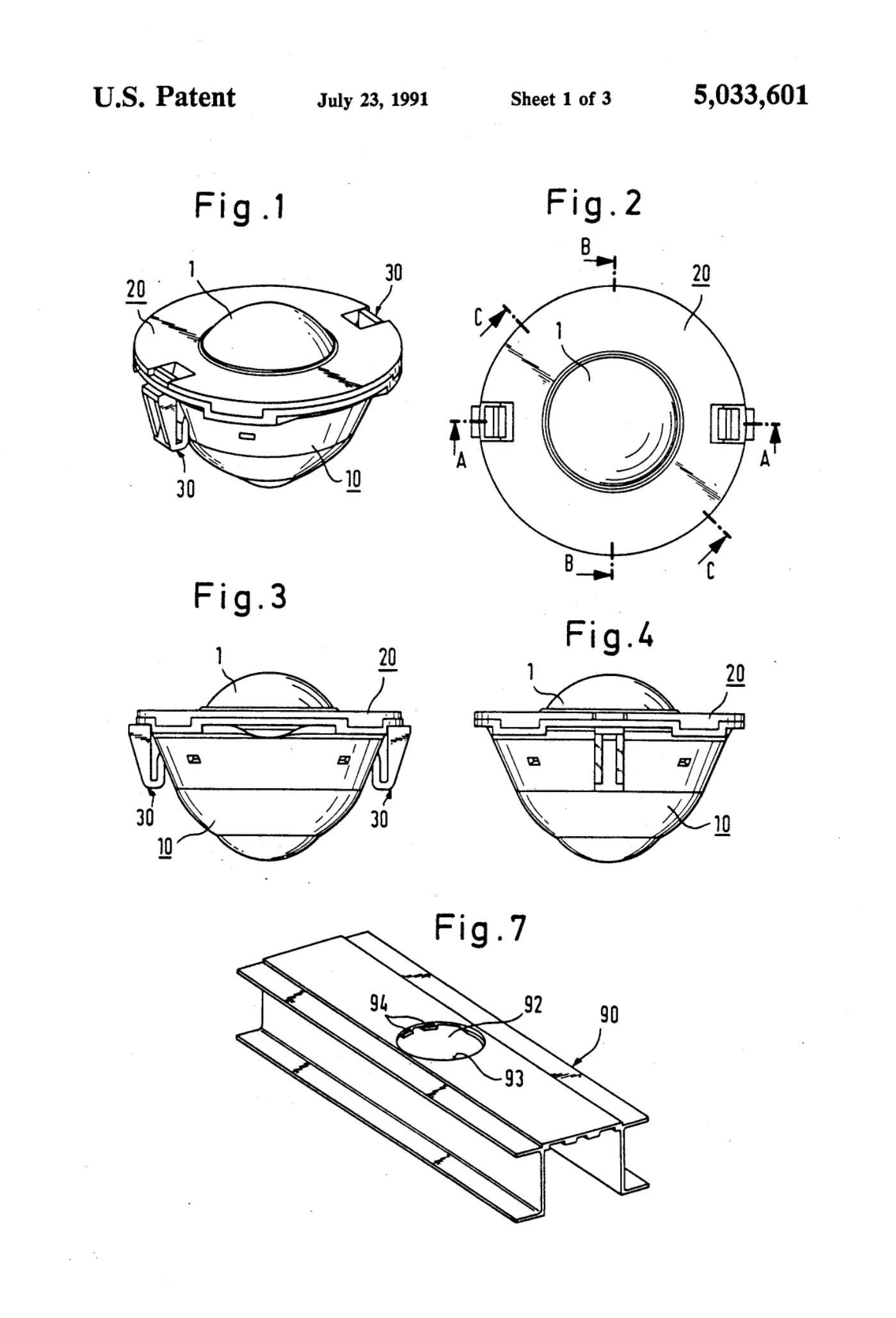
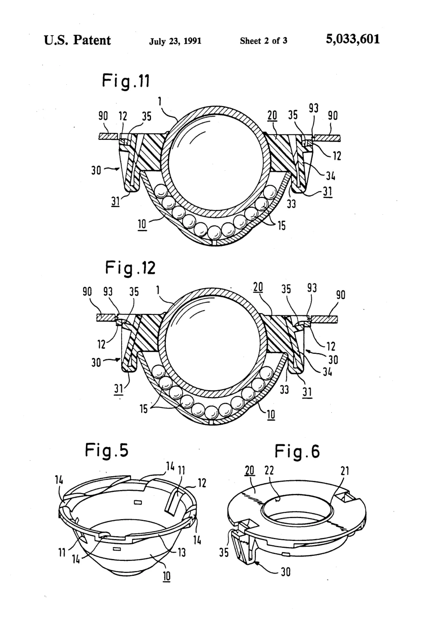
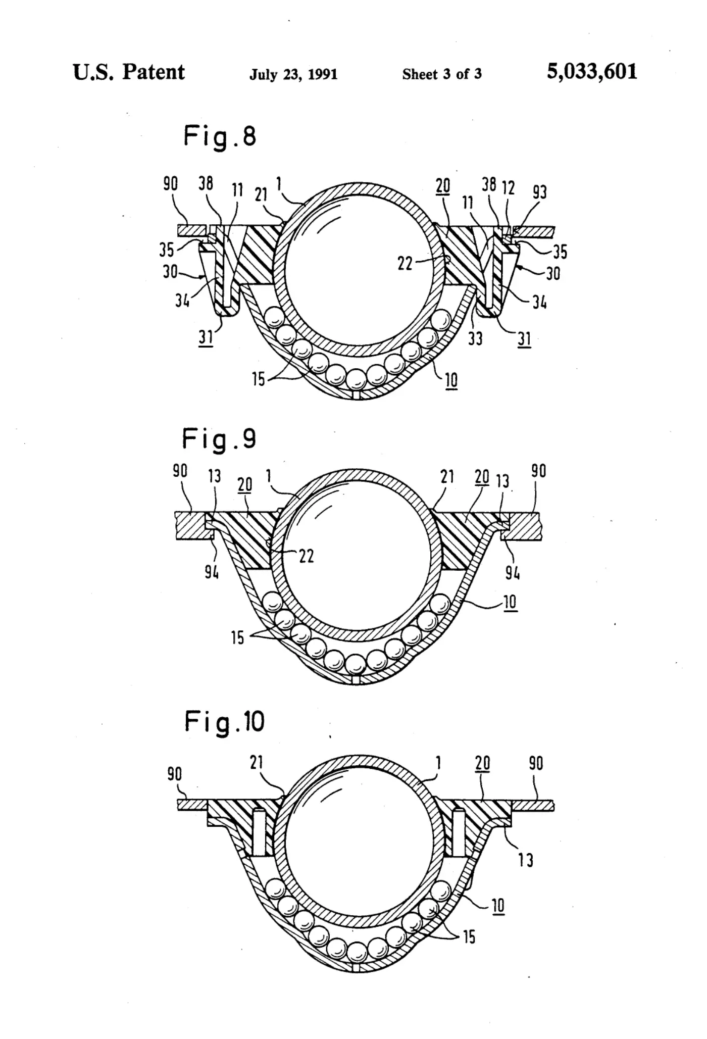
A conveyor ball unit for installation in a mounting opening in a conveyor track panel. A conveyor ball is rotatably mounted on a plurality of mounting balls in a mounting shell and projects upwardly out of the conveyor ball unit. A ball guide of annular configuration embraces the conveyor ball from above to secure the conveyor ball and the mounting balls in the mounting shell. At its peripheral edge the ball guide has at least two locking elements each of which, in the assembled condition of the unit, securingly engages by means of a locking shoulder under a peripheral flange on the mounting shell, to hold the mounting shell and the ball guide together. When the conveyor ball unit is in the installed condition in a conveyor track panel, the peripheral flange of the mounting shell is supported against the peripheral edge of the mounting opening in the conveyor track panel, and the locking shoulders of the locking elements securingly engage with their free outer ends under the peripheral edge of the mounting opening.
Abstract
A conveyor ball unit for installation in a mounting opening in a conveyor track panel. A conveyor ball is rotatably mounted on a plurality of mounting balls in a mounting shell and projects upwardly out of the conveyor ball unit. A ball guide of annular configuration embraces the conveyor ball from above to secure the conveyor ball and the mounting balls in the mounting shell. At its peripheral edge the ball guide has at least two locking elements each of which, in the assembled condition of the unit, securingly engages by means of a locking shoulder under a peripheral flange on the mounting shell, to hold the mounting shell and the ball guide together. When the conveyor ball unit is in the installed condition in a conveyor track panel, the peripheral flange of the mounting shell is supported against the peripheral edge of the mounting opening in the conveyor track panel, and the locking shoulders of the locking elements securingly engage with their free outer ends under the peripheral edge of the mounting opening.
1. Drawings
[0001]Sheet 1.
[0002]Sheet 2.
[0003]Sheet 3.
Publication information
Citation
OpenTechnical Publication OT-2026-000003424, “Conveyor ball unit,” published September 15, 2026 at 20:25:52 UTC, https://opentechnical.org/p/OT-2026-000003424.
To cite specific content, add the paragraph or figure numbers.
Terms
This record reproduces a document published elsewhere and is provided for reference and study. Rights in the original remain with its owner. See the publication policy.