OT-2026-000003473
Device for handling workpieces
- Published
- Permanent URL
- https://opentechnical.org/p/OT-2026-000003473
- Classification
- Tools & Tooling › Clamping Tools
- Inventors
- STOLL KURT
- Assignee
- STOLL KURT
- Original source
- US-4858976-A, the United States Patent and Trademark Office, 22 August 1989
- Document SHA-256
- f90194846bd73d924f68cd46703d9c0be5cf1856035403583a9f5d4b6436a7a8
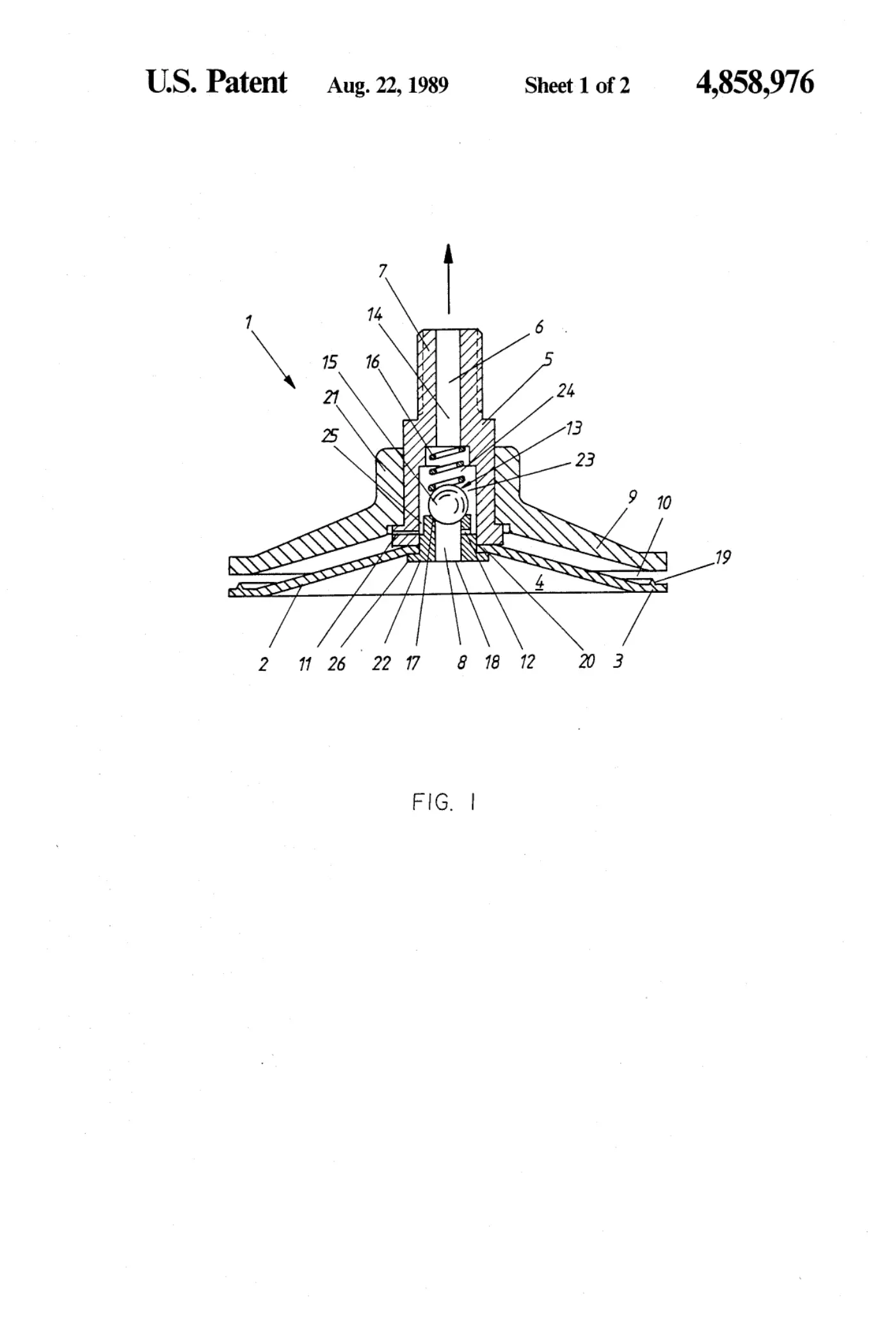
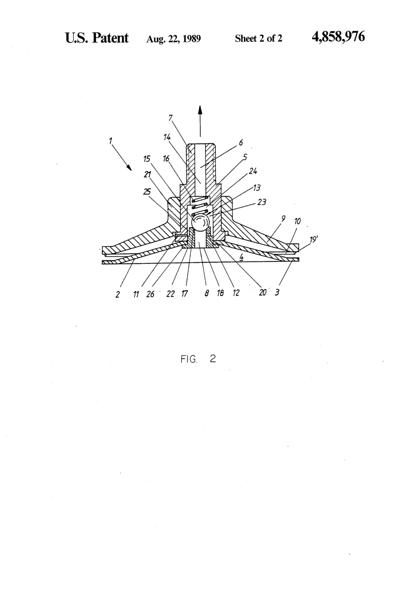
A suction holder for workpieces comprises a suction plate of flexible material which is open towards the workpiece on which it is to be placed. A connector extending away from the workpiece from the central part of the suction plate contains a suction duct opening into the suction chamber so that the latter may be connected with the vacuum line. There is a sensor plate adjacent to the suction plate with a spacing between them and there is also a free annular gap between them opening to the outside. On placing the holder on the workpiece the suction plate is deformed towards the sensor plate and rests against it. In the suction duct there is a check valve closing towards the suction chamber and loaded so as to be normally closed. The annular gap and the suction chamber are connected independently from the check valve via a sensor duct with the suction duct section over the check valve. The cross section of the two sensor ducts is smaller than that of the orifice part of the suction duct. If there is a leak into the suction chamber and/or the annular gap external air will be drawn in via the respective sensor duct when the check valve is shut. When the suction chamber and the annular gap are sealed off the check valve opens for drawing the holder against the workpiece.
Abstract
A suction holder for workpieces comprises a suction plate of flexible material which is open towards the workpiece on which it is to be placed. A connector extending away from the workpiece from the central part of the suction plate contains a suction duct opening into the suction chamber so that the latter may be connected with the vacuum line. There is a sensor plate adjacent to the suction plate with a spacing between them and there is also a free annular gap between them opening to the outside. On placing the holder on the workpiece the suction plate is deformed towards the sensor plate and rests against it. In the suction duct there is a check valve closing towards the suction chamber and loaded so as to be normally closed. The annular gap and the suction chamber are connected independently from the check valve via a sensor duct with the suction duct section over the check valve. The cross section of the two sensor ducts is smaller than that of the orifice part of the suction duct. If there is a leak into the suction chamber and/or the annular gap external air will be drawn in via the respective sensor duct when the check valve is shut. When the suction chamber and the annular gap are sealed off the check valve opens for drawing the holder against the workpiece.
1. Drawings
[0001]Sheet 1.
[0002]Sheet 2.
Publication information
Citation
OpenTechnical Publication OT-2026-000003473, “Device for handling workpieces,” published September 15, 2026 at 20:32:01 UTC, https://opentechnical.org/p/OT-2026-000003473.
To cite specific content, add the paragraph or figure numbers.
Terms
This record reproduces a document published elsewhere and is provided for reference and study. Rights in the original remain with its owner. See the publication policy.