Abstract
An end effector for magnetic end-of-arm tooling for ferrous workpieces is described. The tool comprises a mounting flange (10), a magnet assembly (12), a contact detector (14). The arrangement addresses starting the vacuum at the right moment in the approach, where evacuating before the face touches the workpiece wastes air and pulls dust into the circuit, and evacuating late leaves the tool pressing on a workpiece it has not yet gripped. The description covers what detects contact, what that detection starts, and the order of the two events. Every connection is stated with the medium it carries, and the operating sequence is given as conditions on named operations.
1. Technical Field
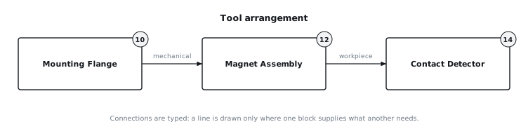
[0001]This disclosure relates to magnetic end-of-arm tooling for ferrous workpieces. It concerns the arrangement of a gripping interface, the supply that feeds it, the distribution and control between them, and the sequence in which those parts act on a workpiece. FIG. 1 shows the arrangement as a block diagram with the reference numerals used throughout this description.
2. Technical Context
[0002]The arrangement addresses starting the vacuum at the right moment in the approach. The difficulty is that evacuating before the face touches the workpiece wastes air and pulls dust into the circuit, and evacuating late leaves the tool pressing on a workpiece it has not yet gripped. A tool that does not address it is still usable on a narrow range of workpieces, and the cost appears as cycle time, dropped parts or air consumption rather than as an outright failure. What follows covers what detects contact, what that detection starts, and the order of the two events.
3. System Overview
[0003]The tool comprises the mounting flange (10), the magnet assembly (12), the contact detector (14). FIG. 1 shows how these blocks are connected and which medium each connection carries. The blocks are not interchangeable by name: a connection is made only where one block offers a medium that another needs, and each connection below is stated together with the medium it carries.
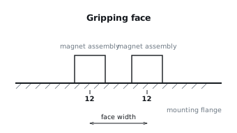
[0004]FIG. 2 shows elevation of the gripping face on its mounting.
[0005]
- The mounting flange is bolted to the robot flange (10).
[0006]
- The coil is supplied from the electrical supply of the cell (12).
[0007]
- The magnet assembly is carried on the mounting flange (12).
[0008]
- The detector watches the magnet assembly and reports when a workpiece is present at that face (14).
4. Components
[0009]Mounting Flange (10). The mounting flange (10) is provided once in this arrangement. The flange carries the whole assembly and presents the bolt pattern that meets the robot.
[0010]Magnet Assembly (12). The magnet assembly (12) is provided once in this arrangement. The face presents a magnetic pole to the workpiece and holds it without any air circuit. The face uses a electromagnet.
[0011]Contact Detector (14). The contact detector (14) is provided once in this arrangement. The detector watches the face and reports the moment a workpiece is present against it. The detector is placed on the gripping face.
5. Operation
[0012]The operating sequence is given as conditions on named operations. Each condition names the event it depends on and the operation it governs, so the order of events is explicit rather than implied by the order of the sentences. FIG. 2 shows the gripping face referred to in these steps. The tool is presented to the workpiece square to the face, and the numbered operations below are what the arrangement does from that point.
[0013]
- When the gripper reaches the gripping position, the coil is energised.
[0014]
- While the coil is in the energised state, the workpiece is held.
[0015]
- After the workpiece has reached the set-down position, the coil is shut down.
[0016]
- After the contact detector has detected the workpiece, the gripping cycle is actuated.
[0017]An operation whose condition is not met does not run. A condition that is stated with UNLESS holds except while its event is true, and one stated with UNTIL ends the operation at the moment its event becomes true. With the workpiece released, the tool returns to the pick position and the cycle repeats.
6. Example Embodiments
[0018]In one embodiment the gripping face carries 1 magnet assemblys on a common mounting, fed as shown in FIG. 1, and the tool is presented to the workpiece square to the face. In a second embodiment the same face is arranged in two rows so that a long workpiece is supported at both ends, with the connections of FIG. 1 unchanged. In a third embodiment the face is built at half the pitch and the number of magnet assemblys is doubled for the same envelope, which suits a workpiece that is lighter but less rigid.
7. Alternative Configurations
[0019]The magnetic face may be replaced by a vacuum face for workpieces that are not ferrous, at the cost of an air circuit and a sealing surface. An isolation valve may be added in the line to each zone, which allows one part of the face to be cut from the circuit while the rest holds its vacuum.
8. Parameter Variations
[0020]Each parameter below is stated with what it changes in the arrangement. The magnet type of the magnet assembly is electromagnet in the arrangement described; varying it changes whether the holding force can be switched off at all, and what happens on power loss. The placement of the contact detector is on the gripping face in the arrangement described; varying it changes whether contact is reported for the face as a whole or for one part of it.
9. Additional Implementations
[0021]A pressure sensor may be tapped into the circuit so that the state of the grip is observable, and the motion that follows the grip may be made conditional on the level it reports. The whole assembly may be carried on a tool-change interface so that it can be exchanged between jobs without dismantling the tool. The face may be divided into zones, each fed by its own branch, so that a workpiece covering part of the face is handled without the uncovered part being held under vacuum. The arrangement may be duplicated on one mounting so that two workpieces are handled in one cycle, with the distribution fed from a common inlet and each face controlled on its own.
10. Provenance and method
[0022]This document is an original combination composed from a typed library of mechanism blocks. Each block was derived from the published patent literature and carries typed connection points, the parameters its source states, and its own construction and operating description. The combination described here is proposed rather than taken from any one source, and it is not asserted to have been constructed. The published documents behind the blocks used in this arrangement are US-10259123-B2, US-10549431-B2, US-2022339798-A1. Their text is not reproduced here; the description above is generated from the structure of the combination.
11. Figures