Abstract
This disclosure describes a tool changer coupling system incorporating redundant locking detection mechanisms independent of the actuator state. The problem addressed is the potential for tool drops when a coupling reports locked solely based on actuator position, without confirming mechanical engagement of the locking elements. The described system employs two distinct detection paths: one responsive to the actuator position and another directly sensing the mechanical seating of the locking elements. Disagreement between these paths or loss of pneumatic supply initiates a safe condition, preventing unintentional tool release and enhancing operational integrity in robotic applications.
1. Technical Field
[0001]The present disclosure relates to robotic end-effector exchange systems, specifically focusing on mechanisms for coupling and uncoupling tools to a robotic arm. More particularly, it concerns tool changer designs that incorporate enhanced reliability in detecting the locked state of the coupling, independent of the primary actuation mechanism.
2. Technical Context
[0002]In automated manufacturing and assembly, robotic systems frequently require the ability to change end-effectors, such as grippers, welders, or paint guns, to perform diverse tasks. A tool changer system facilitates this by providing a standardized interface between the robot arm and various tools. A critical aspect of tool changer operation is the secure mechanical locking of the tool-side mount (12) to the robot-side mount (10) following an exchange. Failure of this locking mechanism or inaccurate detection of its status can lead to the unintended release of a tool, potentially causing damage to the tool, the workpiece, or the surrounding environment, and posing safety risks.
[0003]A common failure mode in existing tool changer systems arises when the coupling mechanism relies solely on the position of its actuation device to infer the locked state. For example, if a pneumatic cylinder (16) is commanded to extend to a "locked" position, and a sensor (18) confirms the cylinder's extension, the system might report a locked condition. However, mechanical obstructions, wear, or foreign debris could prevent the actual locking elements (14) from fully engaging, even if the actuator (16) has completed its stroke. This discrepancy means the system believes the tool is securely attached, while in reality, it is only loosely held or not engaged at all, creating a risk of the tool dropping during subsequent robot motion. The present disclosure addresses this by providing redundant detection paths, ensuring that both the actuator's intended state and the actual mechanical engagement of the locking elements are confirmed before a locked status is reported.
3. System Overview
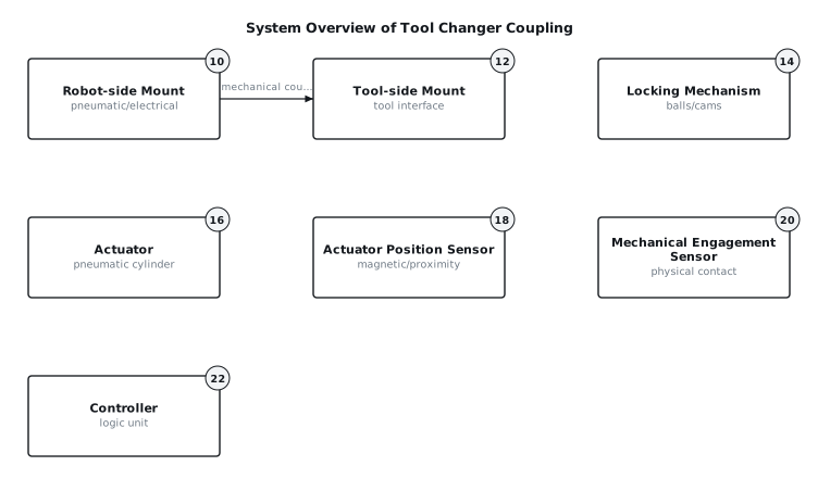
[0004]The described system comprises a robot-side mount (10) intended for attachment to a robotic arm, and a tool-side mount (12) designed to interface with various tools. The two mounts engage mechanically and are secured by a locking mechanism (14), typically actuated by a pneumatic cylinder (16). To ensure reliable operation and prevent unintended tool release, the system incorporates two independent detection paths to confirm the locked status. The first path utilizes an actuator position sensor (18) to verify that the actuator (16) has completed its stroke corresponding to the locked position. The second, and distinct, path employs a mechanical engagement sensor (20) that directly detects the physical seating or displacement of the locking elements (14) themselves, indicating actual mechanical interlock. A control unit (22) processes signals from both sensors. For the system to report a "locked" status, both detection paths must concurrently indicate a locked condition. Disagreement between the two sensors, or a loss of pneumatic supply, triggers a fault condition and maintains the coupling in a safe, mechanically secured state where possible, or prevents further operation if unlocking is commanded. FIG. 1 provides a block diagram illustrating the primary components and their interconnections within this system.
4. Components
[0005]The primary components of the tool changer coupling system include:
[0006]
- Robot-side Mount (10): This structural component attaches to the robot arm. It houses the actuator (16), the locking mechanism (14), and typically provides pneumatic and electrical pass-through connections to the tool-side mount (12). It features an interface face with recesses or channels designed to receive the locking elements (28) when coupled.
- Tool-side Mount (12): This component attaches to the tool or end-effector. It features a corresponding interface face with mating features, such as a tapered receptacle (32) and a circumferential groove, designed to mechanically engage with the locking elements (28) of the robot-side mount (10).
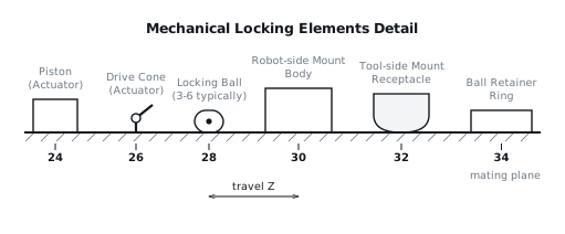
- Actuator (16): Typically a double-acting pneumatic cylinder, the actuator provides the motive force to move the locking mechanism (14) between its locked and unlocked states. It consists of a piston (24) and a drive cone (26) or similar mechanical linkage.
- Locking Mechanism (14): This mechanism consists of multiple locking balls (28), typically three to six, arranged circumferentially around the axis of the coupling. These balls are retained by a ball retainer ring (34) or similar structure and are pushed radially outward by the drive cone (26) of the actuator (16) to engage with a mating groove in the tool-side mount (12). When the actuator (16) retracts, the drive cone (26) moves away, allowing the balls (28) to retract radially inward, releasing the tool-side mount (12).
- Actuator Position Sensor (18): This sensor provides an indication of the actuator's (16) physical position. For a pneumatic cylinder, this is commonly a magnetic reed switch or a Hall effect sensor that detects the presence of a magnet embedded in the cylinder's piston (24). It provides a binary signal indicating whether the piston is at the 'locked' end-of-stroke or 'unlocked' end-of-stroke.
- Mechanical Engagement Sensor (20): This sensor directly detects the physical state of the locking elements (14). It is independent of the actuator position sensor (18). One implementation involves a small plunger or lever that is displaced only when at least one of the locking balls (28) is fully seated in the circumferential groove of the tool-side mount (12). This displacement then actuates a miniature proximity sensor, limit switch, or optical sensor. Alternatively, a sensor might detect the position of the ball retainer ring (34) or a similar component that moves only when the balls (28) are fully engaged.
- Controller (22): This electronic control unit receives signals from both the actuator position sensor (18) and the mechanical engagement sensor (20). It processes these signals according to predefined logic to determine the overall status of the coupling (locked, unlocked, or fault) and communicates this status to the main robot controller.
- Pneumatic Supply Lines: These lines deliver compressed air to the actuator (16) for its operation. A pressure sensor (not shown) on the pneumatic supply line can be integrated to detect air loss.
[0007]FIG. 2 illustrates an elevation view showing the interaction of the locking balls with the tool-side mount and the actuator.
5. Operation
[0008]The operation of the tool changer system involves distinct phases: tool pickup, steady-state operation (locked), and tool release, with specific considerations for fault conditions and air loss.
[0009]Tool Pickup and Locking:
[0010]
- Initial State: The robot-side mount (10) is in the "unlocked" state, meaning the actuator (16) is retracted, allowing the locking balls (28) to be in their radially inward position, ready to receive a tool. Both the actuator position sensor (18) and the mechanical engagement sensor (20) indicate "unlocked."
- Mating: The robotic arm moves the robot-side mount (10) to align with and mate to the tool-side mount (12). The tapered receptacle (32) of the tool-side mount guides the robot-side mount into position.
- Actuation: Once fully mated, the controller (22) commands the actuator (16) to extend. The piston (24) and drive cone (26) move forward, pushing the locking balls (28) radially outward into the circumferential groove of the tool-side mount (12).
- Detection and Confirmation:
- As the actuator (16) reaches its extended position, the actuator position sensor (18) changes state, indicating "actuator locked position reached."
- Simultaneously, or shortly thereafter, as the locking balls (28) fully seat into the tool-side mount's (12) groove, the mechanical engagement sensor (20) changes state, indicating "mechanical locking engaged."
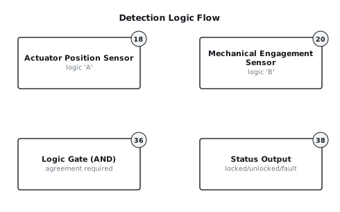
- Locked Status Report: The controller (22) receives both signals. If both sensors (18) and (20) confirm a locked condition, the controller (22) reports "LOCKED" to the robot control system. This dual confirmation, as illustrated in FIG. 3, ensures that the tool is physically secure before any further robot motion is permitted.
[0011]Steady-State Operation (Locked): During normal operation, the tool changer remains in the locked state. Both the actuator position sensor (18) and the mechanical engagement sensor (20) continuously report "locked." The controller (22) monitors these signals. If either signal unexpectedly reverts to "unlocked" while the system is commanded to be locked, a fault condition is immediately triggered.
[0012]Tool Release and Unlocking:
[0013]
- Command to Unlock: The robot control system sends an "UNLOCK" command to the controller (22).
- Actuation: The controller (22) commands the actuator (16) to retract. The drive cone (26) moves backward, allowing the locking balls (28) to retract radially inward, disengaging from the tool-side mount (12).
- Detection and Confirmation:
- As the actuator (16) retracts, the actuator position sensor (18) changes state, indicating "actuator unlocked position reached."
- As the locking balls (28) fully disengage, the mechanical engagement sensor (20) changes state, indicating "mechanical locking disengaged."
- Unlocked Status Report: If both sensors (18) and (20) confirm an unlocked condition, the controller (22) reports "UNLOCKED."
[0014]Fault or Interruption (Disagreement or Air Loss):
[0015]
- Sensor Disagreement: If, during a locking operation, the actuator position sensor (18) indicates "locked" but the mechanical engagement sensor (20) indicates "unlocked" (or vice versa), the controller (22) registers a "FAULT" condition. In this scenario, the controller (22) does not report "LOCKED" and typically prevents the robot from moving the tool, prompting operator intervention or automatically re-attempting the locking sequence. During steady-state operation, if a disagreement occurs, the system assumes an unsafe state and immediately stops robot motion, typically signaling a critical error. The system is designed such that the locking mechanism (14) has a mechanical bias to stay locked if the actuator (16) is in the locked position, requiring active force to unlock.
- Air Loss (Pneumatic Failure): The actuator (16) is designed to be fail-safe locked. This means that upon a loss of pneumatic pressure, the locking mechanism (14) defaults to or remains in the mechanically locked state if it was previously locked. This is typically achieved through spring-biasing the piston (24) towards the locking position or by designing the geometry of the drive cone (26) and balls (28) such that a constant radial force maintains engagement once locked, with pneumatic pressure required only to unlock the system. In such a scenario, the actuator position sensor (18) might indicate an abnormal state (e.g., intermediate position), but the mechanical engagement sensor (20) would continue to report "locked." The controller (22) would interpret this as an "AIR LOSS - LOCKED" fault, indicating a problem but confirming mechanical retention of the tool, preventing an accidental drop. If air loss occurs during an unlocking attempt, the system would immediately halt the unlocking sequence, ensuring the tool remains coupled, and report an appropriate fault.
6. Example Embodiments
[0016]Embodiment 1 This embodiment utilizes a pneumatic cylinder (16) as the actuator. The actuator position sensor (18) is a magnetic reed switch mounted externally to the cylinder body, detecting a magnet embedded in the piston (24) at its fully extended (locked) position. The mechanical engagement sensor (20) is a miniature inductive proximity sensor positioned to detect the presence of a metal tab integrated into the ball retainer ring (34). This tab becomes detectable by the inductive sensor only when the locking balls (28) are fully seated and the retainer ring (34) has shifted to its corresponding position. The controller (22) is a programmable logic controller (PLC) or a dedicated microcontroller.
[0017]Embodiment 2 In this configuration, the actuator (16) is still pneumatic, but the actuator position sensor (18) is an optical sensor that detects a flag attached to the end of the piston rod (24) when it reaches the locked position. The mechanical engagement sensor (20) is a series of miniature snap-action limit switches, one for each locking ball (28). Each limit switch is positioned such that its plunger is depressed only when the corresponding locking ball (28) is fully engaged in the tool-side mount's (12) groove. The controller (22) then requires all individual ball switches to be activated for a "mechanical locked" signal. This provides granular detection of engagement across multiple locking elements.
[0018]Embodiment 3 This embodiment employs an electric servo motor (not shown) as the actuator (16), which drives a cam mechanism to actuate the locking balls (28). The actuator position sensor (18) is an encoder integrated into the servo motor, providing precise angular position feedback. The mechanical engagement sensor (20) consists of an array of through-beam optical sensors. Each sensor pair is aligned across a small gap where a portion of a locking ball (28) passes when fully engaged. When the ball (28) is fully seated, it breaks the beam, indicating engagement. The controller (22) processes the encoder feedback and the optical sensor signals.
7. Alternative Configurations
[0019]The locking mechanism (14) itself can be configured in various ways. Instead of locking balls (28), the system could use a set of radially expanding jaws or cam-actuated fingers that engage with corresponding features on the tool-side mount (12). The principle of redundant detection would still apply: one sensor (18) confirms the actuator's (16) extended position, and a second sensor (20) confirms the physical engagement of the jaws or fingers. For example, a small lever could be integrated into one of the jaws, actuating a microswitch when the jaw is fully seated. Similarly, the actuator (16) could be an electrically driven solenoid or an electromechanical screw jack, requiring appropriate end-of-stroke detection for the actuator position sensor (18). The interface between the robot-side mount (10) and tool-side mount (12) can also vary, for instance, incorporating an additional central alignment pin for precise angular orientation, with the locking mechanism (14) providing axial retention.
8. Parameter Variations
| Parameter | Range | Effect of Increasing Value | Effect of Decreasing Value |
|---|---|---|---|
| Number of Locking Balls | 3 to 6 | Increased load distribution, potentially higher overall retention force. | Reduced load distribution, lower overall retention force, simpler mechanism. |
| Ball Diameter | 8 mm to 20 mm | Higher contact area, greater shear strength, potentially larger overall coupling size. | Smaller contact area, lower shear strength, potentially smaller overall coupling size. |
| Actuator Stroke | 10 mm to 30 mm | Greater travel for locking elements, potentially more robust engagement/disengagement. | Shorter travel, faster action, but potentially less margin for error in engagement. |
| Pneumatic Pressure | 0.4 MPa to 0.7 MPa | Stronger locking/unlocking force, faster actuation. | Weaker locking/unlocking force, slower actuation, potentially unreliable engagement. |
| Sensor Redundancy Logic | AND (both required) to OR (either) | Higher safety, requires full confirmation, more prone to false negatives (faults). | Lower safety, permits operation with partial confirmation, less prone to false negatives. |
| Disagreement Time Threshold | 50 ms to 500 ms | Longer allowance for mechanical settling before fault, potentially slower fault detection. | Faster fault detection, potentially more prone to transient false positives. |
| Coupling Diameter | 50 mm to 200 mm | Higher payload capacity, larger physical footprint. | Lower payload capacity, smaller physical footprint, faster acceleration/deceleration. |
| Materials (e.g., Balls) | Hardened steel to Ceramic | Higher wear resistance, higher cost, potentially higher weight. | Lower wear resistance, lower cost, potentially lighter weight. |
9. Additional Implementations
[0021]The redundant detection principle can be extended beyond basic locked/unlocked status. For instance, an additional set of proximity sensors could be integrated to detect the presence of the tool-side mount (12) before the locking sequence initiates, ensuring that the robot-side mount (10) is correctly positioned and fully seated axially. This prevents the actuator (16) from attempting to lock when no tool is present, or when the tool is misaligned, thereby reducing wear and potential damage. Furthermore, the controller (22) could incorporate predictive maintenance features by monitoring the time difference between the actuator position sensor (18) changing state and the mechanical engagement sensor (20) changing state. An increasing delay could indicate wear, debris accumulation, or pneumatic system degradation, allowing for proactive maintenance before a critical fault occurs. The system could also integrate environmental sensors, such as temperature or humidity sensors, to compensate for material expansion/contraction or prevent operation in extreme conditions that could affect mechanical tolerances or sensor performance. The communication between the controller (22) and the main robot system can be implemented using various fieldbus protocols or discrete I/O, ensuring compatibility with a wide range of industrial automation architectures.
10. Figures