Abstract
This disclosure details a mechanism for extending the effective payload capacity and preserving acceleration characteristics of a Delta robot by counterweighting its upper arm linkage. Delta robots typically experience a significant reduction in achievable acceleration with increasing payload due to the inherent inertia of their parallel kinematic arms. The described arrangement introduces a passive counterweight system dynamically coupled to each upper arm, offsetting a substantial portion of the arm's inertial mass and a fraction of the payload. This method aims to maintain higher dynamic performance across a broader payload range, impacting cycle time and reachable workspace.
1. Technical Field
[0001]The technical field relates to industrial robotics, specifically to parallel kinematic manipulators, and more particularly to Delta robot architectures. It concerns methods for enhancing the dynamic performance and payload capacity of such robots.
2. Technical Context
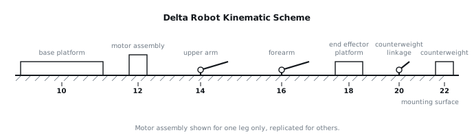
[0002]Delta robots are widely utilized for high-speed pick-and-place operations due to their high stiffness, low moving inertia, and direct-drive motor architectures. The typical Delta robot consists of a fixed base platform (10) to which three or more parallel kinematic chains are connected. Each chain comprises an upper arm (14) driven by a motor assembly (12) mounted on the base platform (10), and a forearm (16) connected to the upper arm (14) at a passive joint. The forearms (16) converge to connect to a common end effector platform (18). The low moving mass inherent to this design allows for high acceleration and deceleration rates, contributing to fast cycle times.
[0003]However, as the required payload increases, the overall inertia of the moving parts, including the arms and the payload, also increases. The inertia of the upper arms (14) themselves constitutes a significant portion of this total moving inertia, especially when considering the rotational inertia about their pivot points on the base platform (10). This increased inertia directly opposes the motor torque, leading to a substantial reduction in achievable acceleration and, consequently, slower cycle times for a given motor size. This limitation curtails the maximum effective payload at which the robot can operate within desired performance parameters. Addressing this limitation without resorting to larger, heavier, and more power-intensive motor assemblies is a key objective for optimizing robot performance and energy efficiency.
3. System Overview
[0004]The disclosed system enhances the dynamic performance of a Delta robot by incorporating a passive counterweight mechanism into each of its upper arm linkages. The core principle involves offsetting the inertial contribution of the upper arm (14) and a portion of the payload through the strategic placement of a counterweight (22). As illustrated in FIG. 1, a counterweight (22) is mechanically coupled to each upper arm (14) via a counterweight linkage (20). This linkage (20) is designed to ensure that the counterweight (22) moves in a coordinated fashion with the upper arm (14), providing a counter-moment that reduces the effective inertial load on the motor assembly (12) responsible for driving that arm.
[0005]Each motor assembly (12) drives a respective upper arm (14) which pivots about an axis on the base platform (10). The counterweight linkage (20) attaches to the upper arm (14) at a point offset from its primary pivot, and the counterweight (22) is fixed at the end of this linkage (20). The geometry of the counterweight linkage (20) is chosen such that the angular acceleration of the counterweight (22) about the upper arm's pivot point generates an inertial moment opposing the moment generated by the upper arm (14) and any attached payload. This arrangement aims to reduce the net torque demand on the motor assembly (12) during acceleration and deceleration phases, thereby allowing for higher accelerations for a given motor size or enabling the use of smaller motors for a specified performance. The system operates passively, relying solely on mechanical coupling and inertial forces, thus avoiding the need for additional sensors or active control loops for the counterweight function itself.
4. Components
[0006]The primary components of the system are detailed as follows:
[0007]
- Base Platform (10): A rigid structural frame providing mounting points for the motor assemblies (12) and the kinematic chains. It defines the fixed reference frame for the robot's operation.
- Motor Assembly (12): Comprising a motor, gearbox (if present), and an encoder, responsible for driving the angular position of each upper arm (14). Three or more such assemblies are typically employed.
- Upper Arm (14): A rigid link, typically fabricated from a lightweight, stiff material such as aluminum alloy or carbon fiber composite. It pivots at one end on the base platform (10) and connects to a forearm (16) at the other. It is the primary element whose inertia is targeted for compensation.
- Forearm (16): A pair of rigid links forming a parallelogram, connecting the upper arm (14) to the end effector platform (18). These links are passively articulated, allowing translation of the end effector platform (18) without rotation.
- End Effector Platform (18): A platform to which a gripper, suction cup, or other tooling is attached. It is positioned by the combined action of the parallel kinematic chains.
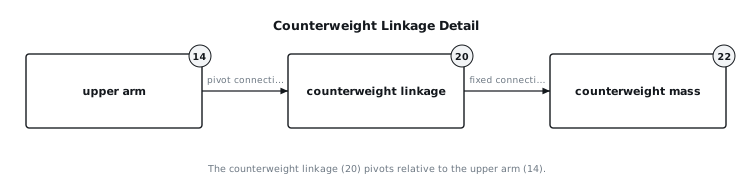
- Counterweight Linkage (20): A rigid link, as shown in FIG. 2, designed to transfer the motion of the upper arm (14) to the counterweight (22). It is pivotally attached to the upper arm (14) at a specific point along its length or to an extension thereof.
- Counterweight (22): A mass, typically made from a dense material such as steel, tungsten, or lead alloy. Its mass and position are engineered to provide the desired inertial compensation. It is rigidly attached to the counterweight linkage (20).
- Bearings (24): Low-friction bearings are used at all pivot points, including the main pivot of the upper arm (14) on the base platform (10), the connection between the upper arm (14) and the forearm (16), and the connection between the counterweight linkage (20) and the upper arm (14).
- Structural Mounts (26): Components used to securely attach the counterweight (22) to the counterweight linkage (20) and the counterweight linkage (20) to the upper arm (14).
5. Operation
[0008]The system operates by dynamically balancing the inertial forces associated with the upper arm (14) and payload during robot motion.
[0009]Start-up: Upon power-up, the robot performs a homing sequence. During this sequence, the motor assemblies (12) drive the upper arms (14) to a known reference position. The counterweight (22) moves in tandem with its respective upper arm (14) via the counterweight linkage (20). The system is designed to not interfere with the homing procedure.
[0010]Steady Running: During normal operation, the motor assemblies (12) command specific angular trajectories for the upper arms (14) to achieve the desired end effector platform (18) position and velocity. As an upper arm (14) rotates, the counterweight linkage (20) causes the counterweight (22) to also rotate, as shown in FIG. 1. The mass and geometry of the counterweight (22) and counterweight linkage (20) are selected such that the moment of inertia provided by the counterweight (22) about the upper arm's pivot point on the base platform (10) partially or fully cancels the moment of inertia of the upper arm (14) itself and a specified portion of the payload. This reduces the effective inertial load on the motor assembly (12) during angular acceleration and deceleration of the upper arm (14). The reduction in required motor torque for a given acceleration allows for either higher accelerations with existing motor sizing or the ability to handle larger payloads while maintaining previous acceleration profiles.
[0011]Fault or Interruption: In the event of a fault, such as an emergency stop or power loss, the motor assemblies (12) are typically de-energized, and brakes (if equipped) may engage. The counterweight system is passive, meaning it does not introduce additional active control failure modes. However, a specific failure mode relates to the counterweight linkage (20) becoming loose or detached. If a counterweight linkage (20) or counterweight (22) detaches during operation, the inertial properties of the affected arm (14) will change abruptly. This will result in an immediate increase in the torque required to accelerate or decelerate that arm, potentially leading to position tracking errors, motor overcurrent conditions, and activation of safety stops. The robot's control system, monitoring motor currents and position errors, is expected to detect such an anomaly and initiate a controlled shutdown. Due to the potential for an uncontrolled mass to be ejected, protective guarding around the robot's workspace is a critical safety consideration.
6. Example Embodiments
[0012]Embodiment 1 In this configuration, each counterweight linkage (20) is designed as a simple rigid rod, pivotally attached to the upper arm (14) near its base, specifically at a point approximately one-quarter of the upper arm's length from its pivot on the base platform (10). The counterweight (22) is a solid cylindrical mass fixed at the distal end of the counterweight linkage (20). The length of the counterweight linkage (20) is approximately 0.2 times the length of the upper arm (14). This embodiment focuses on providing a direct inertial counter-moment, where the counterweight (22) largely moves within the same plane as the upper arm (14). The counterweight (22) mass is set to approximately 70% of the upper arm's mass.
[0013]Embodiment 2 This embodiment employs a more complex counterweight linkage (20) that is shaped as a curved arm, designed to allow the counterweight (22) to trace an arc that keeps it closer to the base platform (10) throughout the upper arm's (14) range of motion. The counterweight linkage (20) pivots from a point on the upper arm (14) that is approximately one-third of the upper arm's length from its base pivot. The curved geometry ensures that the counterweight (22) does not significantly extend the overall footprint of the robot's motion envelope while providing an effective counter-moment. The counterweight (22) mass is approximately 85% of the upper arm's mass, allowing for compensation of a portion of the payload inertia in addition to the arm's own inertia.
[0014]Embodiment 3 In this embodiment, the counterweight (22) is an adjustable mass assembly. The counterweight linkage (20) is a telescopic or sliding mechanism, allowing the effective moment arm of the counterweight (22) to be varied. This adjustment enables fine-tuning of the inertial compensation for different payload ranges. For instance, for heavier payloads, the counterweight (22) can be extended further from the pivot point on the upper arm (14), increasing its effective moment of inertia contribution. Conversely, for lighter payloads, it can be retracted. The counterweight linkage (20) attaches to the upper arm (14) via a bracket at approximately half the upper arm's length. The counterweight (22) mass is approximately 60% of the upper arm's mass, with an adjustable extension range of 0.1 to 0.3 times the upper arm's length.
7. Alternative Configurations
[0015]Several alternative configurations can be considered. Instead of a single counterweight (22) per arm, a distributed mass system could be integrated along the counterweight linkage (20) or even within a hollow upper arm (14) structure, if practicable, to optimize the mass distribution. The counterweight linkage (20) itself could be an integral extension of the upper arm (14) rather than a separate component, simplifying assembly but reducing adjustability. Furthermore, the counterweight (22) could be made from a material with tunable density, such as a composite structure with internal cavities that can be filled or emptied with a fluid or granular material, providing an active adjustment capability without mechanical repositioning. The pivot point for the counterweight linkage (20) on the upper arm (14) could also be adjustable, allowing for alteration of the kinematic relationship between the upper arm (14) and the counterweight (22).
8. Parameter Variations
| Parameter | Range | Effect of Moving Towards Upper End of Range | Effect of Moving Towards Lower End of Range |
|---|---|---|---|
| Counterweight Mass (22) | 0.5 to 1.5 times upper arm mass | Increased inertial compensation, reduced net motor load, potential for larger payloads, increased overall moving mass. | Reduced inertial compensation, increased net motor load, lower effective payload capacity. |
| Counterweight Linkage Length (20) | 0.1 to 0.4 times upper arm length | Increased effective moment arm of counterweight, greater compensation for a given mass, increased workspace intrusion. | Reduced effective moment arm, less compensation for a given mass, minimal workspace intrusion. |
| Counterweight Pivot Point (on upper arm 14) | 0.2 to 0.8 times upper arm length from base pivot | Higher angular velocity of counterweight for a given upper arm angle, potentially more effective compensation. | Lower angular velocity of counterweight, less effective compensation. |
| Upper Arm Length (14) | 200 mm to 800 mm | Larger reachable workspace, higher inertia, greater demands on counterweight system. | Smaller reachable workspace, lower inertia, reduced demands on counterweight system. |
| Payload Mass | 0.1 kg to 10 kg | Increased motor load, reduced acceleration capacity, higher demand for counterweight compensation. | Reduced motor load, increased acceleration capacity, lower demand for counterweight compensation. |
[0017]The effect on the reachable envelope is primarily influenced by the counterweight linkage length (20) and the form factor of the counterweight (22). A longer counterweight linkage (20) or a bulky counterweight (22) that extends significantly from the upper arm (14) will reduce the reachable envelope by creating interference with the base platform (10), other arms, or the workspace boundaries. Careful design of the counterweight linkage (20) and counterweight (22) geometry, such as the curved linkage in Embodiment 2, can mitigate this reduction. The trade against cycle time is direct: increased inertial compensation allows for higher accelerations, which directly translates to shorter cycle times for operations involving significant movement. Conversely, insufficient compensation will lead to longer cycle times or necessitate lower payloads.
9. Additional Implementations
[0018]The counterweighting principle could be extended to other parallel kinematic manipulators or even serial robots where specific arm segments contribute disproportionately to the total moving inertia. For example, a similar passive counterweighting scheme could be applied to the forearms (16) if their mass contribution becomes significant relative to the payload and upper arms (14). This would involve an additional set of linkages and counterweights for each forearm (16), further reducing the inertial load on the upper arm (14) motors. The counterweight system could also incorporate a spring mechanism to provide an additional bias force, assisting in gravity compensation for vertical movements, further reducing the continuous torque demand on the motors, especially for applications where the robot frequently operates in an unfavorable gravitational orientation. Furthermore, the counterweight (22) could be designed with an aerodynamic profile to minimize air resistance at high operating speeds, or with a damping mechanism to suppress any resonant vibrations that might arise from its dynamic interaction with the upper arm (14).
10. Figures