Abstract
A zero-gravity balancer arrangement for manipulating objects in three-dimensional space is disclosed. The arrangement includes an end effector with an integrated grip sensor that detects operator contact. A control system monitors both the grip sensor state and the vertical velocity of the end effector. When the grip sensor indicates disengagement, the balancer transitions from an unconstrained float mode to a rate-limited descent or ascent, preventing uncontrolled vertical drift of a slightly imbalanced load. This approach addresses the problem of loads "running away" when inadvertently released by an operator, enhancing safety and control during handling operations.
1. Technical Field
[0001]This disclosure relates to systems for manipulating objects, specifically to zero-gravity balancers and manipulators that assist an operator in lifting, moving, and positioning loads. More particularly, it concerns control strategies for such systems operating in a float mode, aiming to enhance safety and control when an operator disengages from a load.
2. Technical Context
[0002]Industrial manipulators and balancers are designed to counteract the weight of a payload, allowing an operator to move heavy objects with minimal effort. Many such systems incorporate a "zero-gravity" or "float" mode, where the system applies a force equal to the estimated or measured payload weight, effectively making the load weightless. This permits free movement of the load by an operator. A common challenge in these systems arises when the applied balancing force is not precisely equal to the load's weight. Slight imbalances can occur due to variations in payload mass, dynamic effects, or limitations in the balancing mechanism's accuracy. If an operator releases a load that is not perfectly balanced, even a small residual force can cause the load and the end effector to drift vertically in an uncontrolled manner. This uncontrolled movement can pose a safety risk to operators and surrounding equipment, and it makes precise placement difficult if the load "runs away" after release. The problem is exacerbated by the human tendency to release a load when it is approximately in position, but not yet perfectly stable.
3. System Overview
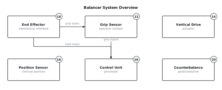
[0003]The disclosed arrangement is a zero-gravity balancer system (FIG. 1) designed to mitigate uncontrolled vertical drift of an end effector (10) when an operator disengages from a load. The system comprises an end effector (10) which provides an interface for gripping or attaching to a load. Integrated within or proximate to the end effector (10) is a grip sensor (12) that detects operator contact or engagement with the end effector (10) or the load itself. A vertical drive (14) provides the necessary force to counterbalance the load and move the end effector (10) vertically. This drive (14) is coupled with a position sensor (16) that continuously monitors the vertical position of the end effector (10). All these components are connected to a control unit (18), which processes inputs from the grip sensor (12) and position sensor (16) to generate commands for the vertical drive (14). A counterbalance mechanism (20), which can be passive or active, assists the vertical drive (14) in supporting the load. The core innovation lies in the control unit's (18) ability to distinguish between intended operator movement and unintentional drift by utilizing both grip state and vertical velocity, applying a rate bound when operator engagement is not detected.
4. Components
[0004]The primary components of the balancer system are:
[0005]
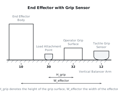
- End Effector (10): This is the mechanical interface that directly interacts with the load. It can be a hook, a clamp, a vacuum gripper, or any other suitable attachment mechanism. It is designed to transmit forces to and from the load and to provide a surface for operator interaction, often incorporating handles or grip points (32) as shown in FIG. 3. The mass of the end effector (10) itself is considered in the overall balancing calculation.
- Grip Sensor (12): This sensor detects the presence or absence of an operator's hand or body contact with the end effector (10) or designated grip surfaces (32). It may be a capacitive sensor, a resistive sensor, a force-sensitive resistor (FSR) array, an optical sensor, or a mechanical switch. The sensor (12) provides a binary or analog signal to the control unit (18) indicating operator engagement. For example, a capacitive sensor might output a high signal when a human hand is detected, and a low signal when no hand is present.
- Vertical Drive (14): This component is responsible for generating the vertical force required to support and move the load. It typically consists of an electric motor coupled to a gearbox and a lifting mechanism, such as a wire rope drum, a chain hoist, or a lead screw. A pneumatic cylinder or a hydraulic cylinder may also be employed. The drive (14) is commanded by the control unit (18) to apply specific forces or achieve specific velocities or positions.
- Position Sensor (16): This sensor measures the vertical position of the end effector (10). Common types include rotary encoders attached to the drive motor or drum, linear potentiometers, or ultrasonic distance sensors. The position data is fed to the control unit (18) and is used to calculate vertical velocity.
- Control Unit (18): This is the central processing element of the system. It typically includes a microcontroller or digital signal processor (DSP) along with associated power electronics and communication interfaces. It receives sensor inputs, executes control algorithms, and generates output commands for the vertical drive (14). Its functions include load estimation, mode management, and safety monitoring.
- Counterbalance (20): This mechanism provides a substantial portion of the balancing force, reducing the demands on the vertical drive (14). It can be a passive system, such as a spring, a gas cylinder, or a counterweight, or an active system that continuously adjusts its force. The control unit (18) can issue commands to an active counterbalance to fine-tune its contribution.
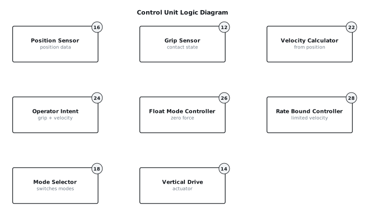
- Velocity Calculator (22): (FIG. 2) A software module within the control unit (18) that derives the instantaneous vertical velocity of the end effector (10) from the position data provided by the position sensor (16). This is typically achieved through differentiation and filtering of the position signal over time.
- Operator Intent Module (24): (FIG. 2) A logical block within the control unit (18) that processes the grip sensor (12) signal and the calculated vertical velocity (22) to determine if the operator is actively engaging with and moving the load.
- Float Mode Controller (26): (FIG. 2) The control algorithm responsible for maintaining a zero-gravity state. It typically applies a force equal to the estimated load weight, allowing free movement.
- Rate Bound Controller (28): (FIG. 2) The control algorithm that limits the vertical velocity of the end effector (10) to a predefined maximum rate when active.
- Mode Selector (18, functionally): (FIG. 2) A logic block within the control unit (18) that switches the operational mode of the vertical drive (14) between the float mode and the rate-bounded mode based on the output of the operator intent module (24).
- Load Attachment Point (30): (FIG. 3) The specific point or mechanism on the end effector (10) where the object to be manipulated is physically connected.
- Operator Grip Surface (32): (FIG. 3) A designated area on the end effector (10) designed for operator interaction, often shaped for ergonomic gripping. This surface is where the grip sensor (12) is typically integrated.
5. Operation
[0006]The system operates in several distinct phases: initialization, active manipulation (float mode), and disengagement (rate-bound mode or static hold).
[0007]Initialization: Upon power-up, the control unit (18) performs self-diagnostics. The vertical drive (14) may be commanded to a home position. The system typically enters a standby mode, often with the vertical drive (14) maintaining a minimum upward force to support the end effector (10) itself. If an active counterbalance (20) is present, it will be set to a default or minimal force. The system may prompt for a load attachment or a teach sequence to estimate the initial load mass.
[0008]Active Manipulation (Float Mode): When an operator approaches the end effector (10) and engages the grip surface (32), the grip sensor (12) registers contact. The operator intent module (24) interprets this as active engagement. If a load is attached (either known or estimated), the system transitions to float mode. In this mode, the float mode controller (26) commands the vertical drive (14) and potentially the active counterbalance (20) to exert an upward force precisely equal to the combined weight of the end effector (10) and the load. This creates a "zero-gravity" condition, allowing the operator to move the load vertically with minimal effort. The velocity calculator (22) continuously provides vertical velocity data, which, along with the grip sensor (12) signal, is used by the operator intent module (24) to confirm active manipulation. For instance, if the grip sensor (12) is active and the vertical velocity is non-zero, it is interpreted as operator-intended movement.
[0009]Disengagement and Rate-Bound Mode: When the operator releases the grip surface (32), the grip sensor (12) signal changes state, indicating disengagement. At this point, the operator intent module (24) signals to the mode selector (18) that active manipulation has ceased. The mode selector (18) then transitions the control of the vertical drive (14) from the float mode controller (26) to the rate bound controller (28).
[0010]The rate bound controller (28) immediately takes over. Instead of maintaining an exact zero-gravity balance, it switches to a velocity control strategy. If the load is not perfectly balanced (i.e., there is a residual upward or downward force), it will begin to drift. However, the rate bound controller (28) will actively limit this vertical velocity to a predefined maximum rate, V_max_drift. For example, if the load begins to descend due to a slight imbalance, the controller (28) will allow it to descend, but only at a velocity not exceeding V_max_drift (e.g., 0.05 m/s). Conversely, if the load begins to ascend, it will be allowed to ascend at a rate not exceeding V_max_drift. This prevents the load from "running away" vertically while still permitting slow, controlled movement.
[0011]Behavior on Load Release at Height: If an operator releases a load at an elevated height, and the grip sensor (12) indicates disengagement, the system immediately enters the rate-bound mode. If the load is perfectly balanced, it will remain stationary or drift slowly within the V_max_drift limits. If there is a slight imbalance, the load will slowly ascend or descend at the bounded rate. This controlled movement allows the operator to re-engage the load if necessary, or provides a predictable slow descent/ascent to a resting position without sudden drops or uncontrolled ascents. The system may also include a timeout feature, where after a specified duration (e.g., 5 seconds) in rate-bound mode without re-engagement, it transitions to a static hold mode, where the vertical drive (14) actively maintains the current position, or gently lowers the load to a predetermined safe position.
[0012]Fault or Interruption: In the event of a power failure or a critical system fault detected by the control unit (18), the vertical drive (14) is typically designed to safely arrest movement. This might involve engaging a mechanical brake or using residual power to slowly lower the load to the ground, or engaging the counterbalance (20) if it is passively engaged. The grip sensor (12) signal can also serve as an emergency stop input if a rapid release is detected during high-speed movement.
6. Example Embodiments
[0013]Embodiment 1: A balancer system for handling automotive sub-assemblies, featuring an end effector (10) with an integrated array of force-sensitive resistors (FSRs) as the grip sensor (12) beneath an ergonomic grip surface (32). The FSRs are configured to detect the presence of an operator's hand by sensing pressure above a threshold (e.g., 5 N). The vertical drive (14) consists of an electric servo motor driving a lead screw. The control unit (18) implements a rate bound of 0.03 meters per second (m/s) in disengaged mode. When the FSR array detects release, the system checks the current vertical velocity from the position sensor (16). If the velocity exceeds 0.03 m/s, the servo motor is commanded to reduce the velocity to within this bound. If the velocity is below this bound, it is allowed to continue at that rate. After 10 seconds of continuous disengagement, the system initiates a slow, controlled descent at 0.02 m/s until it reaches a lower limit switch, where it enters a static hold.
[0014]Embodiment 2: A balancer system for handling large panel sections in a cleanroom environment, utilizing a vacuum gripper as the end effector (10). The grip sensor (12) is a capacitive proximity sensor located on the main body of the end effector (10) near the operator's control interface, rather than directly on a grip surface. The vertical drive (14) uses a pneumatic cylinder for primary lift and an electromechanical linear actuator for fine positioning. When the capacitive sensor detects operator disengagement, the control unit (18) transitions to a rate-bound mode with an allowed drift velocity of 0.08 m/s. The pneumatic cylinder provides the bulk of the balancing force, while the linear actuator actively limits any drift to the specified rate. In this embodiment, after 3 seconds of disengagement, the system enters a static hold, maintaining the current height, to prevent any contamination from prolonged movement.
[0015]Embodiment 3: A balancer system for assembly tasks involving small, delicate components, where the end effector (10) is a set of precision tweezers. The grip sensor (12) is integrated into the finger-actuated levers of the tweezers, using micro-switches that activate upon operator grip pressure. The vertical drive (14) is a small, high-precision stepper motor with a ball screw. Due to the delicate nature of the loads, the rate bound is set to a very low value, such as 0.01 m/s. Upon release, if the tweezers are holding a component, the system immediately applies a small braking force to halt any vertical movement and holds position indefinitely unless the operator re-engages or a manual override is activated. If no component is detected by the tweezers (e.g., via a secondary force sensor at the load attachment point (30)), the system behaves as in the rate-bound mode.
7. Alternative Configurations
[0016]The grip sensor (12) could be implemented as an array of optical sensors detecting hand presence, or as a set of mechanical switches that are actuated by the operator's hand. Instead of being integrated into the end effector (10), the grip sensor (12) could be a wearable device on the operator that communicates wirelessly with the control unit (18). The vertical drive (14) may be augmented with a secondary, emergency brake mechanism that engages mechanically if the drift rate exceeds a critical threshold or if power is lost. The counterbalance (20) could be an entirely active system, such as a secondary motor precisely controlled by the control unit (18) to provide the balancing force, allowing the main vertical drive (14) to focus solely on movement and rate bounding. The velocity calculation (22) could be performed by a dedicated hardware module for faster response times instead of solely in software.
8. Parameter Variations
| Parameter | Realistic Range | Effect of Moving Towards Lower End | Effect of Moving Towards Upper End |
|---|---|---|---|
V_max_drift (rate bound) | 0.01 to 0.1 m/s | Slower, more controlled drift; potentially longer time to settle. | Faster, less controlled drift; quicker reaction required from operator. |
| Grip Sensor Threshold Force | 2 to 15 N | More sensitive to light touches; potential for false positives. | Less sensitive; requires firm grip; potential for delayed detection. |
| Disengagement Timeout | 1 to 15 seconds | Quicker transition to static hold or controlled descent. | Longer period of rate-bounded drift before full stop. |
| Load Mass Range | 5 to 500 kg | Easier to balance; less powerful drive required. | More challenging to balance; more powerful drive and robust structure. |
| Vertical Travel Range | 0.5 to 5 meters | Suitable for confined spaces; simpler drive mechanics. | Greater operational flexibility; more complex drive and cable management. |
| Position Sensor Resolution | 0.1 to 1 mm | Higher precision in position and velocity; more accurate control. | Lower precision; potential for oscillations or less smooth movement. |
| Control Loop Update Rate | 50 to 500 Hz | Slower response to changes; less stable control. | Faster response; smoother control; higher computational demand. |
9. Additional Implementations
[0018]This rate-bounded float mode can be adapted for horizontal movements in multi-axis manipulators. In such a configuration, a grip sensor (12) on the horizontal axis end effector (10) would, upon disengagement, limit the horizontal drift velocity to a predefined H_max_drift rather than allowing free, uncontrolled movement. The principle can also be applied to systems where gravity compensation is partial, for example, in underwater manipulators or space applications where residual forces are present. The grip sensor (12) input could be combined with other sensor data, such as proximity sensors on the end effector (10), to provide context-aware behavior. For instance, if the grip sensor (12) indicates release and a proximity sensor detects an obstacle below, the rate-bound mode could be overridden by an immediate halt or a slight ascent. Furthermore, the system could incorporate a "gentle lower" feature where, upon disengagement and after a short delay, the rate bound actively guides the load to the nearest stable surface or a predetermined safe height at a very slow, controlled descent rate, even if it is not perfectly balanced. The rate bound itself could also be dynamically adjusted based on the estimated load mass, with heavier loads having a tighter (lower) V_max_drift for increased safety.
10. Figures