Abstract
A system for localized recovery of a robot within a cube storage grid is disclosed, addressing the problem of grid-wide operational halts due to a single robot malfunction. This arrangement defines a dynamic isolation zone around a faulty robot or jammed bin lift, rerouting adjacent operational robots to maintain throughput in unaffected areas. It includes provisions for a manual access path into the isolation zone for intervention and a structured process for reconciling the state of the recovered robot and the grid control system upon fault resolution, thereby minimizing system downtime and operational disruption.
1. Technical Field
[0001]The present disclosure relates to automated storage and retrieval systems (AS/RS), and more particularly to cube-based storage systems employing autonomous mobile robots operating on a grid structure. Specifically, it concerns methods and systems for recovering from localized faults, such as a jammed bin lift or a stuck robot, without requiring a complete shutdown or evacuation of the entire storage grid.
2. Technical Context
[0002]Automated cube storage systems utilize a dense three-dimensional grid of storage locations for bins, with autonomous robots traversing the top layer of the grid to access and transport these bins. Bins are typically moved vertically within the grid by bin lifts to reach the robots on the top surface or to be stored at lower levels. A common challenge in such systems arises when a single robot or a bin lift experiences a fault, such as a physical jam or a control system error. Current approaches often involve stopping all operations within a significant portion of the grid, or even the entire grid, to ensure safety and allow for diagnostic and recovery procedures. This leads to substantial downtime and reduced system throughput, disproportionate to the localized nature of the fault. There is a need for a system that can isolate such faults and enable recovery actions while permitting the majority of the system to continue operating, thereby improving overall system availability and efficiency.
3. System Overview
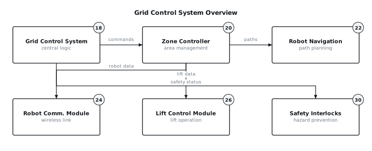
[0003]The disclosed system provides a method for managing and recovering from localized faults within a cube storage grid (14). It comprises a network of autonomous robots (10) operating on the top surface of the grid (14), a multitude of storage bins (12) housed within the grid (14), and multiple bin lifts (16) integrated into the grid (14) for vertical movement of bins (12). A central grid control system (18) oversees all operations, including robot (10) movement, bin (12) storage and retrieval, and bin lift (16) operation. Upon detection of a fault at a specific location, such as a jammed bin lift (16) or a stalled robot (10), the system establishes a dynamic isolation zone around the affected area. This zone is defined by the grid control system (18) and communicated to all operational robots (10) and relevant zone controllers (20). Neighboring robots (10) are then rerouted to avoid the isolation zone, maintaining operational flow in the unaffected regions. The system also defines a safe manual access path (28) into the isolation zone for maintenance personnel. After the fault is resolved and the affected robot (10) or bin lift (16) is cleared, a state reconciliation process is initiated to reintegrate the recovered elements into normal system operation. This approach minimizes the impact of localized faults on overall system performance. FIG. 1 illustrates the interaction between the grid control system (18) and its sub-components.
4. Components
[0004]The system incorporates several key components:
[0005]
- Robot (10): An autonomous mobile robot capable of traversing the top surface of the storage grid (14), lifting and transporting storage bins (12). Each robot (10) includes a drive system, a bin handling mechanism, a local control unit, and a robot communication module (24).
- Storage Bin (12): A container designed to store items, sized to fit within the grid (14) structure and handled by the robots (10) and bin lifts (16).
- Storage Grid (14): A three-dimensional matrix of storage cells designed to hold bins (12). The top layer provides pathways for robots (10).
- Bin Lift (16): A mechanism integrated into the grid (14) structure, capable of moving bins (12) vertically between storage levels and the top robot (10) access layer. Each bin lift (16) is controlled by a local lift control module (26).
- Grid Control System (18): The central software and hardware architecture responsible for managing all operations within the storage grid (14). This includes task assignment, traffic management, fault detection, and recovery coordination. It communicates with all other active components.
- Zone Controller (20): A distributed control unit, often a software module within the grid control system (18) or a dedicated hardware unit, responsible for managing a specific logical or physical section of the grid (14). It handles local robot (10) dispatch, path planning, and conflict resolution within its zone.
- Robot Navigation System (22): A subsystem, typically part of the grid control system (18) or zone controllers (20), responsible for calculating optimal paths for robots (10), managing traffic flow, and detecting potential collisions.
- Robot Communication Module (24): A wireless communication interface on each robot (10) enabling two-way data exchange with the grid control system (18) or zone controllers (20).
- Lift Control Module (26): A local controller for each bin lift (16), responsible for executing vertical movement commands, reporting lift status, and detecting operational anomalies.
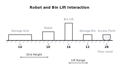
- Maintenance Access Point (28): Designated physical locations or procedures within the grid (14) that allow for safe human access for maintenance or recovery operations. These points may include removable grid sections or dedicated access shafts. FIG. 2 illustrates a robot (10), bin lift (16), and storage bin (12) in relation to the storage grid (14) and a conceptual access point (28).
- Safety Interlocks (30): Hardware and software mechanisms designed to prevent unsafe conditions, such as unauthorized access to active zones or operation of machinery during maintenance.
5. Operation
[0006]The system operates through several distinct phases: normal running, fault detection, isolation, rerouting, recovery, and state reconciliation.
[0007]During normal running, the grid control system (18) assigns tasks to available robots (10), directing them to retrieve or store bins (12). Robots (10) navigate the top grid (14) surface, interacting with bin lifts (16) to move bins (12) vertically. The grid control system (18) continuously monitors the status of all robots (10), bin lifts (16), and grid (14) components through regular status updates from their respective communication modules (24) and control modules (26).
[0008]Fault detection occurs when a robot (10) or bin lift (16) reports an error, or when the grid control system (18) detects a deviation from expected behavior, such as a robot (10) failing to reach a target location within a specified timeout, or a bin lift (16) exceeding its travel time for a given movement. For example, a bin lift (16) jam might be detected by an overcurrent condition in its motor or by position sensors indicating a stalled state.
[0009]Upon fault detection, the grid control system (18) initiates isolation. It identifies the precise location of the fault and defines an isolation zone. This zone is a logical or physical area around the fault location, typically extending a configurable distance, for example, two to four grid cells in each cardinal direction from the immediate fault point. All robots (10) currently within or approaching this zone receive immediate commands to halt or divert. The zone controller (20) responsible for the affected area is notified and updates its local map to mark the isolation zone as restricted.
[0010]Neighboring robots (10) are rerouted by the robot navigation system (22). The grid control system (18) updates its global path planning algorithms to exclude the isolation zone. New paths are calculated for any robots (10) whose current or planned routes intersect the restricted area. This rerouting is dynamic, attempting to minimize travel distance while avoiding the blocked region. Tasks that require access to bins (12) within the isolation zone are temporarily suspended or re-prioritized to other available bins (12).
[0011]For recovery, the grid control system (18) identifies and designates a manual access path (28). This path is a sequence of grid cells from a predefined maintenance entrance to the edge of the isolation zone, and then potentially into the zone itself. Before personnel enter, safety interlocks (30) are engaged to power down or disable any machinery within the isolation zone that could pose a hazard. The grid control system (18) communicates the precise boundaries of the access path and the isolation zone to the maintenance team. Personnel can then enter to diagnose and resolve the fault, for example, by manually clearing a bin lift (16) jam or repositioning a stuck robot (10).
[0012]Once the fault is cleared and the affected robot (10) or bin lift (16) is verified to be in a safe and operational state, state reconciliation begins. Personnel signal the grid control system (18) that the fault is resolved. The system then performs a series of checks:
[0013]
- Component Status Verification: The recovered robot (10) or bin lift (16) undergoes a diagnostic self-test, reporting its operational status and current position to the grid control system (18).
- Grid State Update: The grid control system (18) updates its internal model to reflect the new state of the recovered component. If a bin (12) was involved, its location and status are confirmed.
- Isolation Zone Deactivation: The isolation zone is gradually deactivated. This may involve a temporary "buffer zone" phase where robots (10) are allowed to approach but not enter at full speed, or a direct full release.
- Task Reassignment: Any tasks that were previously suspended due to the fault and are now accessible are re-queued or reassigned to available robots (10).
- Traffic Reintegration: The robot navigation system (22) begins to incorporate the previously restricted paths back into its planning, allowing robots (10) to resume normal traffic patterns through the area.
[0014]In the event of an unrecoverable fault or interruption that cannot be localized, the system is designed to perform a controlled shutdown of the affected zone or the entire grid (14), ensuring the safety of personnel and equipment before maintenance operations can proceed.
6. Example Embodiments
[0015]Embodiment 1 In this embodiment, the isolation zone is established as a fixed-size exclusion area around the fault location. For instance, if a robot (10) jams at a specific grid coordinate, the isolation zone is always defined as a 5x5 cell square centered on that coordinate. The grid control system (18) marks all cells within this fixed zone as impassable for all other robots (10). The manual access path (28) is predefined for each potential fault location, linking it to the nearest maintenance access point. State reconciliation involves a simple binary flag: "fault active" or "fault cleared". Once cleared, the entire fixed zone is immediately reopened for traffic. This embodiment prioritizes simplicity and rapid deployment.
[0016]Embodiment 2 This embodiment utilizes a dynamically sized isolation zone. The dimensions of the zone are determined by the nature of the fault, the type of component involved, and the potential hazard radius. For example, a minor sensor fault on a robot (10) might trigger a 1x1 cell exclusion zone, while a bin lift (16) jam involving a dropped bin (12) might create a larger 7x7 cell zone that extends vertically through multiple levels. The grid control system (18) uses a rule-based engine to compute the optimal zone size and shape. The manual access path (28) is also dynamically calculated, considering current grid traffic and available maintenance access points (28) to provide the quickest and safest route. State reconciliation in this embodiment includes a phased reintroduction of the area, where the zone is first reduced to a smaller exclusion area for diagnostic passes by a designated robot (10), followed by full reintegration after verification.
[0017]Embodiment 3 This embodiment incorporates a dedicated recovery robot or specialized tool. When a fault occurs, the grid control system (18) dispatches a designated recovery robot (not shown) to the edge of the isolation zone. This recovery robot may be equipped with diagnostic sensors, manipulators, or towing capabilities. It can enter the isolation zone, either autonomously or under remote human guidance, to attempt initial fault resolution, such as nudging a misaligned bin (12) or performing a software reset on a stuck robot (10). This reduces the need for immediate human intervention. If the recovery robot cannot resolve the fault, it can assist in preparing the area for human access, for example, by moving obstacles or activating specific safety procedures. State reconciliation may involve the recovery robot performing initial functional tests on the recovered component before full operational robots (10) are allowed to re-enter.
7. Alternative Configurations
[0018]The communication protocol between robots (10) and the grid control system (18) can be varied, for example, from a Wi-Fi based system to a dedicated ultra-wideband (UWB) network for improved localization and lower latency. The robot (10) drive mechanisms could alternatively employ omnidirectional wheels for enhanced maneuverability in tight grid spaces, rather than differential drive systems. Bin lifts (16) could be configured as shuttle-based systems that transfer bins (12) horizontally to a vertical conveyor, instead of direct vertical lifting mechanisms, which would alter the failure modes and recovery procedures for lift jams. The grid (14) structure could also incorporate built-in inspection cameras at critical junctions, allowing for remote visual assessment of fault conditions before dispatching personnel.
8. Parameter Variations
| Parameter | Range | Effect of Change |
|---|---|---|
| Robot speed | 0.5 to 3.0 m/s | Higher speeds increase throughput but require faster path planning, more responsive collision avoidance, and potentially larger safety margins for stopping, influencing isolation zone size. Lower speeds reduce wear and simplify control. |
| Grid cell size | 300 to 700 mm side length | Smaller cells allow for denser storage but restrict robot (10) and bin (12) dimensions and potentially increase the complexity of navigation and bin lift (16) mechanisms. Larger cells offer more space but reduce storage density. |
| Isolation zone radius (cells) | 1 to 5 grid cells | A smaller radius minimizes the impact on grid operations but may not provide sufficient safety clearance. A larger radius increases safety and working space for recovery but reduces system throughput due to more restricted areas. |
| Communication latency | 10 to 100 ms | Lower latency enables faster fault detection and more immediate robot (10) responses, crucial for dynamic rerouting and emergency stops. Higher latency can lead to delayed reactions and potentially larger required isolation zones. |
| Number of maintenance access points | 2 to 10 per 1000 square meters | More access points reduce the average distance maintenance personnel need to travel to a fault, potentially speeding up recovery times. Fewer access points simplify grid design but can increase response times. |
| Robot battery life | 4 to 12 hours of continuous operation | Longer battery life reduces the frequency of charging cycles, improving overall robot (10) availability. Shorter battery life necessitates more frequent charging, potentially requiring more robots (10) to maintain throughput or more sophisticated charging infrastructure. |
9. Additional Implementations
[0020]The principles of dynamic isolation zones, rerouting, and state reconciliation described herein can be extended to manage other localized faults within the cube storage system. For example, a fault in a specific storage cell, such as a damaged bin (12) or an obstruction, could be isolated similarly, preventing robots (10) from attempting to access that cell until cleared. The system could also be integrated with predictive maintenance algorithms. If a bin lift (16) shows early signs of wear, the system could proactively establish a reduced-speed zone around it or temporarily decommission it for preventative maintenance during off-peak hours, rather than waiting for a complete failure and subsequent emergency recovery. Furthermore, the concept of a manual access path (28) can be generalized to include automated tool delivery paths, where specialized tools or smaller robots are dispatched to the fault location to assist human operators or perform initial diagnostic steps.
10. Figures