Abstract
This disclosure describes a system for compensating for positional and orientational inaccuracies of a mobile robot base prior to executing a precision manipulation task. It addresses the challenge of achieving high-accuracy manipulation with a mobile platform that has inherent limitations in docking repeatability. An arm-mounted vision sensor detects fiducial markers on or near the target workpiece, allowing for real-time calculation of a correction transform. This transform adjusts the planned manipulator trajectory to account for the base's actual pose relative to the target, ensuring precise end-effector placement and orientation, or indicates when the error is too large to proceed safely.
1. Technical Field
[0001]The present disclosure relates to robotic systems, specifically to mobile manipulators performing tasks requiring high positional and orientational accuracy. More particularly, it concerns methods and systems for compensating for inaccuracies in the placement of a mobile base relative to a target workpiece by employing an arm-mounted vision system to correct manipulator trajectories.
2. Technical Context
[0002]Mobile robotic platforms equipped with manipulator arms are utilized in various applications where tasks require interaction with the environment at different locations. These applications range from logistics and inspection to assembly and maintenance. A common challenge arises when a task requires the manipulator arm to interact with a target workpiece or environment feature with high precision, but the mobile base itself cannot reliably achieve the necessary positional and orientational repeatability. For instance, a mobile base (10) may consistently position itself within a tolerance window of ±5 mm in X and Y, and ±2 degrees in rotation, relative to a desired nominal pose. However, the manipulation task might require the end effector (14) to be placed within ±0.1 mm and ±0.05 degrees of a target pose. Directly mapping a pre-planned arm trajectory based on the nominal base pose would lead to significant errors at the end effector (14), rendering the task infeasible. Existing solutions often involve expensive high-precision mobile platforms, complex docking mechanisms, or extensive manual calibration, which can be time-consuming and limit operational flexibility. This disclosure describes an approach that leverages the dexterity and reach of the manipulator arm (12) combined with a local vision system (16) to dynamically adjust for mobile base (10) positioning errors, thereby bridging the gap between mobile base (10) navigation accuracy and manipulator task precision requirements.
3. System Overview
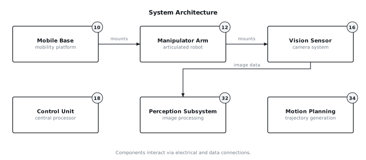
[0003]The described system integrates a mobile base (10) with an articulated manipulator arm (12), an end effector (14), and an arm-mounted vision sensor (16). A central control unit (18) orchestrates the mobile base (10) navigation, manipulator arm (12) motion, and vision-based correction. The process begins with the mobile base (10) navigating to an approximate target location. Once in the vicinity, the manipulator arm (12) repositions the vision sensor (16) to view one or more fiducial markers (20) strategically placed on or near the target workpiece (22). A perception subsystem (32) processes the image data from the vision sensor (16) to accurately estimate the pose of the fiducial markers (20) relative to the vision sensor (16). This information is then used by the control unit (18) to calculate a correction transformation matrix (42). This matrix represents the deviation of the mobile base's (10) actual pose from its assumed nominal pose relative to the target workpiece (22). A motion planning subsystem (34) applies this correction transformation to the pre-planned, nominal manipulator trajectory, effectively shifting and reorienting it in the arm's (12) coordinate frame (28) to compensate for the base's (10) misplacement. This adjusted trajectory is then executed by the manipulator arm (12), ensuring the end effector (14) reaches the intended target pose with the required precision. A safety system (48) monitors the magnitude of the calculated correction; if it exceeds a predefined threshold, indicating an excessive base (10) positioning error, the system will refuse to proceed with the task, preventing potential collisions or failed operations. FIG. 1 illustrates the overall system architecture, showing the interaction between main components.
4. Components
[0004]The system comprises several key components:
[0005]
- Mobile Base (10): This is a wheeled or tracked platform capable of autonomous navigation. It includes a base localization system (44) and a navigation system (46) for approximate positioning. The base (10) provides a stable platform for the manipulator arm (12). Its positioning repeatability is typically in the range of ±2 to ±10 mm and ±0.5 to ±3 degrees.
- Manipulator Arm (12): An articulated robot arm with multiple degrees of freedom, typically five to seven, mounted on the mobile base (10). It is equipped with a kinematics solver (38) that determines joint angles required to achieve a desired end-effector pose, and vice-versa. Its intrinsic accuracy, when operating from a fixed base, is typically within ±0.1 mm and ±0.05 degrees.
- End Effector (14): A tool or gripper attached to the wrist of the manipulator arm (12), designed for interacting with the workpiece (22). The specific design depends on the task, e.g., a gripper for grasping, a tool for processing.
- Vision Sensor (16): A camera system, such as a monochrome or color camera, depth sensor, or stereo camera pair, mounted on the manipulator arm (12), typically near the wrist or end effector (14). It provides image data to the perception subsystem (32). Its field of view and resolution are selected based on the size of the fiducial markers (20) and the required accuracy.## Technical Field
[0006]The present disclosure relates to robotic systems, specifically to mobile manipulators performing tasks requiring high positional and orientational accuracy. More particularly, it concerns methods and systems for compensating for inaccuracies in the placement of a mobile base relative to a target workpiece by employing an arm-mounted vision system to correct manipulator trajectories.
5. Technical Context
[0007]Mobile robotic platforms equipped with manipulator arms are utilized in various applications where tasks require interaction with the environment at different locations. These applications range from logistics and inspection to assembly and maintenance. A common challenge arises when a task requires the manipulator arm to interact with a target workpiece or environment feature with high precision, but the mobile base itself cannot reliably achieve the necessary positional and orientational repeatability. For instance, a mobile base (10) may consistently position itself within a tolerance window of ±5 mm in X and Y, and ±2 degrees in rotation, relative to a desired nominal pose. However, the manipulation task might require the end effector (14) to be placed within ±0.1 mm and ±0.05 degrees of a target pose. Directly mapping a pre-planned arm trajectory based on the nominal base pose would lead to significant errors at the end effector (14), rendering the task infeasible. Existing solutions often involve expensive high-precision mobile platforms, complex docking mechanisms, or extensive manual calibration, which can be time-consuming and limit operational flexibility. This disclosure describes an approach that leverages the dexterity and reach of the manipulator arm (12) combined with a local vision system (16) to dynamically adjust for mobile base (10) positioning errors, thereby bridging the gap between mobile base (10) navigation accuracy and manipulator task precision requirements.
6. System Overview
[0008]The described system integrates a mobile base (10) with an articulated manipulator arm (12), an end effector (14), and an arm-mounted vision sensor (16). A central control unit (18) orchestrates the mobile base (10) navigation, manipulator arm (12) motion, and vision-based correction. The process begins with the mobile base (10) navigating to an approximate target location. Once in the vicinity, the manipulator arm (12) repositions the vision sensor (16) to view one or more fiducial markers (20) strategically placed on or near the target workpiece (22). A perception subsystem (32) processes the image data from the vision sensor (16) to accurately estimate the pose of the fiducial markers (20) relative to the vision sensor (16). This information is then used by the control unit (18) to calculate a correction transformation matrix (42). This matrix represents the deviation of the mobile base's (10) actual pose from its assumed nominal pose relative to the target workpiece (22). A motion planning subsystem (34) applies this correction transformation to the pre-planned, nominal manipulator trajectory, effectively shifting and reorienting it in the arm's (12) coordinate frame (28) to compensate for the base's (10) misplacement. This adjusted trajectory is then executed by the manipulator arm (12), ensuring the end effector (14) reaches the intended target pose with the required precision. A safety system (48) monitors the magnitude of the calculated correction; if it exceeds a predefined threshold, indicating an excessive base (10) positioning error, the system will refuse to proceed with the task, preventing potential collisions or failed operations. FIG. 1 illustrates the overall system architecture, showing the interaction between main components.
7. Components
[0009]The system comprises several key components:
[0010]
- Mobile Base (10): This is a wheeled or tracked platform capable of autonomous navigation. It includes a base localization system (44) and a navigation system (46) for approximate positioning. The base (10) provides a stable platform for the manipulator arm (12). Its positioning repeatability is typically in the range of ±2 to ±10 mm and ±0.5 to ±3 degrees.
- Manipulator Arm (12): An articulated robot arm with multiple degrees of freedom, typically five to seven, mounted on the mobile base (10). It is equipped with a kinematics solver (38) that determines joint angles required to achieve a desired end-effector pose, and vice-versa. Its intrinsic accuracy, when operating from a fixed base, is typically within ±0.1 mm and ±0.05 degrees.
- End Effector (14): A tool or gripper attached to the wrist of the manipulator arm (12), designed for interacting with the workpiece (22). The specific design depends on the task, e.g., a gripper for grasping, a tool for processing.
- Vision Sensor (16): A camera system, such as a monochrome or color camera, depth sensor, or stereo camera pair, mounted on the manipulator arm (12), typically near the wrist or end effector (14). It provides image data to the perception subsystem (32). Its field of view and resolution are selected based on the size of the fiducial markers (20) and the required accuracy.
- Control Unit (18): A central processing unit that manages the overall system. It communicates with the mobile base (10), manipulator arm (12), and vision sensor (16) or its associated perception subsystem (32). It performs calculations for pose estimation, trajectory generation, and safety monitoring.
- Fiducial Marker (20): A visually distinctive pattern or object whose precise dimensions and geometry are known. Examples include AprilTags, ArUco markers, or custom-designed patterns. These markers are placed on or in a known relationship to the target workpiece (22) or the environment feature with which the manipulator arm (12) must interact. They are designed to be easily detectable and accurately localized by the vision sensor (16) under expected lighting conditions.
- Workpiece (22): The object or location upon which the manipulator arm (12) performs its task.
- Perception Subsystem (32): A dedicated processing unit or software module within the control unit (18) that receives image data from the vision sensor (16). It performs image processing, feature extraction, and 2D-to-3D pose estimation to determine the pose of the fiducial markers (20) relative to the vision sensor (16).
- Motion Planning Subsystem (34): Generates joint trajectories for the manipulator arm (12) to move the end effector (14) along a desired path. It takes into account kinematic constraints, collision avoidance, and the calculated correction transformation matrix (42).
- Kinematics Solver (38): A component, typically part of the manipulator arm's (12) controller or the motion planning subsystem (34), that computes forward and inverse kinematics for the manipulator arm (12).
- Pose Estimation Module (40): A software component that computes the 6-DoF pose (position and orientation) of an object (e.g., fiducial marker) from sensor data.
- Correction Transformation Matrix (42): A 4x4 homogeneous transformation matrix representing the offset in position and orientation between the nominal and actual base (10) poses relative to the target workpiece (22).
- Safety System (48): Monitors critical parameters, such as the magnitude of the correction required, and enforces operational limits. If limits are exceeded, it can trigger an emergency stop or prevent task initiation.
- User Interface (50): Provides means for an operator to monitor system status, define tasks, and intervene if necessary.
8. Operation
[0011]The operation of the system involves several distinct phases:
[0012]
- Initial Navigation: The mobile base (10) employs its navigation system (46) and base localization system (44) to drive to a predefined nominal target location. This navigation phase aims to place the mobile base (10) within a capture region where the arm-mounted vision sensor (16) can reliably detect the fiducial markers (20). The expected accuracy at this stage is typically within ±50 mm and ±5 degrees.
- Vision Sensor Positioning: Once the mobile base (10) is approximately positioned, the manipulator arm (12) moves the vision sensor (16) into a pre-programmed "observation pose." This pose is selected to ensure that the fiducial markers (20) on or near the workpiece (22) are within the field of view of the vision sensor (16) and are clearly visible. The observation pose is defined relative to the nominal base (10) pose.
- Fiducial Detection and Pose Estimation: The vision sensor (16) captures one or more images of the fiducial markers (20). The perception subsystem (32) processes these images to identify the markers and determine their 3D pose (position and orientation) relative to the vision sensor's (16) coordinate frame. The accuracy of this pose estimation is influenced by factors such as marker size, sensor resolution, and distance to the marker. This process yields a transformation matrix, T_camera_to_marker.
- Correction Transformation Calculation: The control unit (18) calculates the correction transformation matrix (42). This involves several known transformations:
- T_base_to_arm: The fixed transformation from the mobile base's (10) coordinate frame (26) to the manipulator arm's (12) base frame (28).
- T_arm_to_camera: The known transformation from the manipulator arm's (12) end effector (14) or wrist frame to the vision sensor's (16) frame, determined through camera calibration.
- T_marker_to_workpiece: The known transformation from the fiducial marker's (20) frame to the target workpiece's (22) coordinate frame (30).
- T_nominal_base_to_workpiece: The desired, pre-planned transformation from the nominal base (10) pose to the target workpiece (22).
[0013]The system calculates the actual transformation from the base (10) to the workpiece (22) as: T_actual_base_to_workpiece = T_base_to_arm T_arm_to_camera T_camera_to_marker * T_marker_to_workpiece.
[0014]The correction transformation matrix (42), T_correction, is then calculated as the difference between the nominal and actual transformations in the base's coordinate system (26), or equivalent, the transformation that maps the nominal workpiece pose to the actual workpiece pose relative to the base (10). This can be expressed as: T_correction = T_actual_base_to_workpiece * (T_nominal_base_to_workpiece)^-1.
[0015]This matrix describes the positional and orientational error of the mobile base (10) relative to the ideal placement for the task.
[0016]
- Error Budget and Safety Check: The control unit (18) extracts the translational and rotational components from T_correction. It compares these values against pre-defined maximum allowable error thresholds. For example, if the required correction for translation exceeds 15 mm or rotation exceeds 5 degrees, the safety system (48) determines that the base's (10) positioning error is too large. In such a case, the system aborts the manipulation task and signals a fault via the user interface (50), potentially initiating a re-docking procedure for the mobile base (10) or requiring operator intervention. This prevents the manipulator arm (12) from attempting to reach outside its operational envelope or executing a trajectory with an unacceptably large deviation, which could lead to collisions or damage.
- Trajectory Adjustment and Execution: If the error is within acceptable limits, the motion planning subsystem (34) receives the nominal manipulator trajectory, which was originally planned assuming the mobile base (10) was perfectly at T_nominal_base_to_workpiece. The subsystem (34) then applies the T_correction to each pose within this nominal trajectory. Specifically, for each nominal target pose P_nominal_arm_to_workpiece (defined in the arm's coordinate frame relative to the nominal workpiece position), the corrected target pose P_corrected_arm_to_workpiece is calculated as:
[0017]P_corrected_arm_to_workpiece = (T_base_to_arm)^-1 T_correction T_base_to_arm * P_nominal_arm_to_workpiece.
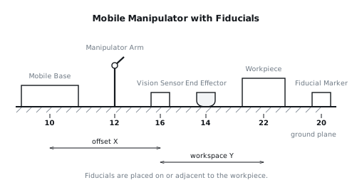
[0018]This corrected trajectory is then sent to the manipulator arm (12) for execution. The kinematics solver (38) translates these corrected poses into joint commands, ensuring the end effector (14) accurately reaches the target points on the workpiece (22). FIG. 2 provides an elevation view of the mobile manipulator and fiducial arrangement.
9. Example Embodiments
[0019]Embodiment 1: A mobile manipulator system for automated pick-and-place operations of small components into precision fixtures. The mobile base (10) navigates to a workstation and docks within ±10 mm and ±2 degrees. The manipulator arm (12) has a reach of 0.8 meters and an intrinsic accuracy of ±0.05 mm. A single high-resolution vision sensor (16) is mounted on the arm's (12) wrist. Four square fiducial markers (20), 50 mm side length, are placed at the corners of a 200 mm by 200 mm area around each fixture, flush with the fixture surface. The vision sensor (16) captures an image from 300 mm above the fixture. The perception subsystem (32) uses sub-pixel edge detection for marker localization, yielding a pose estimation accuracy of ±0.02 mm and ±0.01 degrees. The correction threshold is set to 8 mm translation or 1.5 degrees rotation. If the correction is within these limits, the planned pick-and-place trajectory, originally defined relative to the nominal fixture pose, is adjusted and executed, achieving a final end-effector (14) placement accuracy of ±0.07 mm.
[0020]Embodiment 2: A mobile robot for performing inspection tasks on large industrial machinery. The mobile base (10) positions itself near a machine panel, with a positioning accuracy of ±25 mm and ±3 degrees. The manipulator arm (12) has a long reach, up to 1.5 meters, and carries a vision sensor (16) optimized for structured light. Several circular fiducial markers (20) with a diameter of 100 mm are distributed across the machine panel. The manipulator arm (12) moves the vision sensor (16) to three different observation poses to capture the distributed markers from varying perspectives, allowing for robust 3D reconstruction of the panel's surface and the markers. The perception subsystem (32) triangulates the marker positions to estimate the panel's pose relative to the base (10) with an accuracy of ±0.5 mm and ±0.1 degrees. The correction threshold is set to 20 mm translation or 2.5 degrees rotation. The inspection path, which involves scanning specific features on the panel, is then adjusted using the calculated correction, ensuring full coverage and accurate data acquisition.
[0021]Embodiment 3: A mobile manipulator for collaborative assembly of modular structures. The mobile base (10) approaches a partially assembled structure, aiming for a docking accuracy of ±15 mm and ±1 degree. The manipulator arm (12) is equipped with a stereo vision sensor (16) on its wrist. Prior to assembly, several highly contrasting, uniquely identifiable fiducial markers (20) are affixed to the connection points on the structure. The manipulator arm (12) guides the stereo vision sensor (16) to a single observation pose that captures at least three of these markers. The perception subsystem (32) employs a deep learning-based pose estimation algorithm to identify and localize these markers, providing a pose accuracy of ±0.1 mm and ±0.05 degrees. The correction threshold is set to 12 mm translation or 0.8 degrees rotation. Once the correction is applied, the arm (12) executes a series of precise movements to align and attach new modules to the existing structure. The system also includes a force-torque sensor on the end effector (14) to provide additional feedback during the final mating process.
10. Alternative Configurations
[0022]The fiducial markers (20) are not limited to being placed directly on the workpiece (22). They can be located on a fixture that holds the workpiece (22), on the ground adjacent to the workpiece (22), or on a known environmental feature within the manipulator's (12) workspace. The key requirement is that their position relative to the target interaction points on the workpiece (22) is precisely known. Furthermore, while the vision sensor (16) is described as arm-mounted, it could alternatively be mounted on a separate, dedicated sensor boom extending from the mobile base (10) if the task allows for such a configuration and benefits from a wider, stable field of view, although this would reduce flexibility. The type of vision sensor (16) can vary, including 2D cameras, 3D depth cameras (e.g., time-of-flight or structured light), or stereo camera systems, each offering different trade-offs in accuracy, range, and computational requirements. The fiducial markers (20) themselves can be active (e.g., LEDs) for low-light conditions or passive (e.g., printed patterns) for simplicity. The perception subsystem (32) might employ various algorithms for marker detection and pose estimation, including template matching, geometric fitting, or machine learning-based approaches, depending on the marker design and environmental conditions.
11. Parameter Variations
| Parameter | Range | Effect of increasing value | Effect of decreasing value |
|---|---|---|---|
| Mobile Base Positioning Error | ±5 mm to ±50 mm (translation) | Increases required arm correction, larger risk of exceeding correction threshold. | Decreases required arm correction, less risk of exceeding correction threshold, faster task start. |
| ±0.5 deg to ±5 deg (rotation) | Increases required arm correction, larger risk of exceeding correction threshold. | Decreases required arm correction, less risk of exceeding correction threshold, faster task start. | |
| Vision Sensor Resolution | 0.3 MP to 12 MP | Improves fiducial pose estimation accuracy, enables smaller markers or longer sensing distances. | Degrades fiducial pose estimation accuracy, requires larger markers or shorter sensing distances. |
| Fiducial Marker Size | 10 mm to 200 mm (side/diameter) | Easier detection from further distances, potentially lower relative pose accuracy for small errors. | Harder detection from further distances, potentially higher relative pose accuracy for small errors. |
| Vision Sensor Stand-off Distance | 100 mm to 1000 mm | Larger field of view, lower effective resolution for markers, higher risk of occlusions. | Smaller field of view, higher effective resolution for markers, lower risk of occlusions. |
| Correction Threshold (Translation) | 5 mm to 25 mm | Allows system to operate with larger base errors, higher risk of arm joint limits or collisions. | Requires tighter base positioning, reduces risk of arm joint limits or collisions. |
| Correction Threshold (Rotation) | 1 deg to 10 deg | Allows system to operate with larger base orientation errors, higher risk of arm joint limits. | Requires tighter base orientation, reduces risk of arm joint limits. |
| Manipulator Arm Reach | 0.5 m to 2.0 m | Larger workspace for base positioning, more flexible observation poses for vision sensor. | Smaller workspace for base positioning, more constrained observation poses. |
| Number of Fiducial Markers | 1 to 6 | Increased robustness to occlusion, potentially higher pose estimation accuracy through redundancy. | Reduced robustness to occlusion, lower pose estimation accuracy, simpler setup. |
12. Additional Implementations
[0024]The core concept of arm-side visual correction can be extended to several additional implementations. The system can incorporate a dynamic fiducial detection routine where the manipulator arm (12) actively searches for the fiducial markers (20) if they are not initially within the vision sensor's (16) field of view at the nominal observation pose. This could involve a spiral search pattern or a coarse-to-fine scanning motion. Furthermore, the system can utilize a continuous visual servoing approach after the initial correction. In this mode, the vision sensor (16) continues to monitor the fiducial markers (20) during the execution of the manipulator task, providing real-time micro-adjustments to the arm's (12) trajectory. This can compensate for minor drifts in the mobile base (10) pose or dynamic deformations of the workpiece (22) or environment. For applications requiring manipulation of non-rigid or deformable objects, the fiducial markers (20) could be placed directly on the object itself, allowing the system to adapt to changes in the object's shape or position during the task. The system may also integrate multiple vision sensors (16) or a combination of different sensor types (e.g., a 2D camera for fiducial detection and a 3D LiDAR for environmental mapping and collision avoidance) to enhance robustness and capability. For tasks involving interaction with moving targets, predictive algorithms could be incorporated to estimate future target poses based on observed fiducial motion, allowing the arm (12) to intercept or track the target.
13. Figures